Timing
16 May 2013
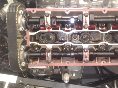
I'd timed in the cams previously (18 months ago! Bloody Hell!) to check clearances, but now it was time to do it for real. Having had my waterpump back, and ordered a new set of pulleys and a belt (itself not easy, as various bits are obsolete or replaced with new part numbers...details and part numbers on the information page), I was ready to go.
Oh, no I wasn't. It seems that a special tool is required to tension the belt. Totally Alfa make a copy of the main dealer tool, which is the only place I've seen that you can get one...otherwise it's guessing time, which doesn't seem like a great idea unless you've done it a few times. That took a couple of weeks to arrive, and in the meantime, I needed to time the cams at least roughly, as you have to be able to turn the engine over to set the belt tension. So I figured I'd set the tension roughly, time the cams, then tension the belt properly, then fine-tune the timing afterwards.
Timing
I didn't go into much detail before as there are many pages describing how to time in a Cam, but when I came to do it this time I'd forgotten lots of the particular detail, so I will go into a bit more depth, just for my own benefit as much as anything else. The lift @ TDC figures are for my Cat Cams fast road cam, not the standard Alfa one.
Timing Procedure from scratch
- Tension belt roughly
- All cam pulley bolts loose
- Find tdc on cylinder 1 (see below)
- Tighten cam pulley bolts 2,3,4 - it helps if the other pulleys are tight as it stops things moving around so much when doing up the one you are adjusting.
- Turn inlet cam for cylinder 1 to just opening, 2.55mm lift. Flats are provided on the cam shaft for a 1" spanner.
- Tighten cam pulley 1 (in)
- Loosen cam pulley 2 (ex)
- Turn Exhaust cam for cylinder 1 to just closing, 2.05mm lift
- Tighten cam pulley 2 (ex)
- Loosen pulleys 3 and 4
- Find tdc on cylinder 5. This is 180 degrees behind cylinder 1 (firing order 1-4-2-5-3-6, each cylinder fires 60 degrees after the previous one (360 degrees crank revolution / 6 cylinders = 60 degrees), so cylinder 5 is 3 cylinders = 180 degrees behind cylinder 1). This means that you can use the same TDC mark as for cylinder one, just turn the engine over one complete revolution.
- Tighten pulley 3
- Turn exhaust cam for cylinder 5 to just closing, 2.05mm lift
- Tighten pulley 4
- Loosen pulley 3
- Turn in cam for cylinder 5 to just opening, 2.55mm lift.
- Tighten all
- Carefully Turn crank through several revolutions to check clearances.
- Check firing order - should be right but make sure that it is correct across the banks, driver's side, then passenger side, 1, 4 then 2, 5 etc.
Finding TDC
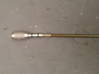
I used a dial guage and crank dial indicator. I also needed to make an extension for the dial guage to reach down the spark plug hole and touch the piston. As it happened, I had a couple of bits of scrap bar which were just the right size, so I superglued them together to make a sliding fit extension:
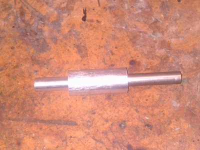
This slides into the spark plug hole, and the dial test indicator is placed on the top:
Then I used the following method: Turn the engine back and forth over tdc, and find the maximum reading on the DTI. This gives you the maximum height of the piston, but it will dwell at this height for several degrees of crank rotation. So to find the actual TDC, you measure two points either side of TDC, and take the centre.
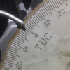
Zero the dial gauge. Then turn the engine forwards so that the piston drops 0.4 mm (i.e 40 divisions on the DTI). Take the reading from the degree wheel on the crank. Then turn the engine backwards, until the piston drops 0.4 mm the other side of TDC. Take the reading from the degree wheel. True TDC is halfway between the two degree readings.
Measuring Cam Lift
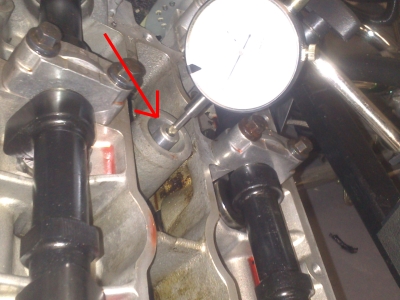
Once TDC is found, move the dial guage so that it's resting on the top of the cam follower for the cylinder concerned. As before, a bent ally wire extension is needed to work around the camshaft itself: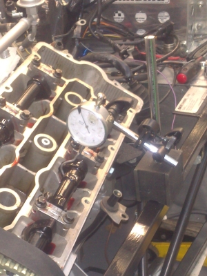
The dti is zeroed with the cam is on its base circle (zero lift), then the cam turned (it has flats for a 1" / 25mm spanner) until the dti reads the required amount of lift. (2.55mm for the inlets, 2.05 for the exhaust). Then tighten up the pulley bolt and on to the next one.
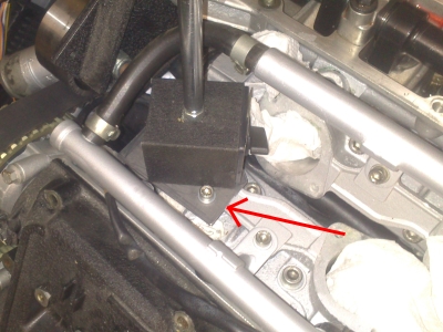
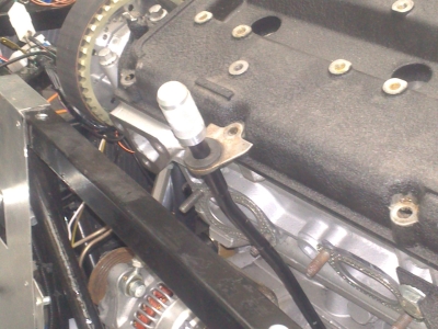
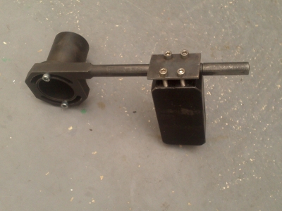
For the exhausts, the dti can be mounted on the chassis rail as shown above. For the inlets, the mount isn't long enough, and it's hard to mount the magnetic base on the ally engine! So I made up a steel plate which bolts onto the inlet port, to provide a mounting point:
Tensioning
First step is to compress the tensioner and hold the piston in place with a pin - a small drill works, as does an allen key:
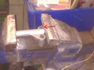 Piston fully compressed - note allen key inserted into rigging hole (arrowed) to retain piston in compressed position
(Must get a new camera - mine broke and I'm using my phone, which is why the pictures aren't great.) Note that a vice is needed to compress the tensioner - you can't do it by hand. If you can get it to move at all by hand, it's knackered. Which will be a shame as they are rather hard (and expensive - 500 US dollars!) to come by.
Then install the tensioner, with the pin still in, and let the tensioner pully assembly rest against the piston.
The tensioner pulley is mounted on an offset spindle, so can be moved to press against the belt by a varying amount. The special tool attaches to the two offset holes in the pulley, and pulls it against the belt by the correct amount (whilst the rest of the tensioner assembly remains resting against the piston). In theory, you then do up the tensioner pully to lock it in position, release the pin from the tensioner and all should be well. However in practice it's rather more complicated...
You set up the special tool, mount it on the pully, then the engine is turned over twice, by hand. The weighted tool has to remain horizontal - if it moves, it has to be readjusted and start again. When it's right, the pulley bolt is then tightened to 55ftlB torque, the pin removed from the piston, the engine turned over twice, again, leave it for at least 10 minutes for the tensioner piston to equilise, then the gap between the piston and pulley assembly lever is measured:
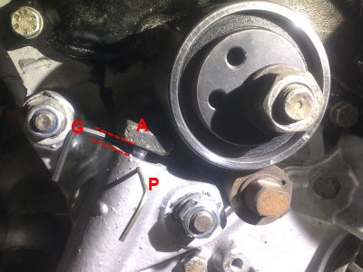 (A) - pulley assembly lever; (P) Rigging Pin; (G) Gap
According to the Alfa technical bulletins on this, there are two measurements, which ensure that the gap G is between 3.1 and 3.6mm; firstly, the rigging pin must be able to be pushed into the hole in the piston body and through the piston. Secondly, the gap (G) must be at least as big as 1/8" inch (here measured using a hex key as a feeler gauge. If either of these criteria are not met, the tension is wrong and "the belt is likely to fail in service". So, a 0.5mm window, adjusted using delicate tools like 2 foot torque wrenches.
So if the gap is wrong (likely), you have to adjust the tool (the weight can be slid back and forth to adjust the tension it puts on the belt), and go through the whole process again. I now have a theory that the reason these engines were known to suffer early cambelt failure, is that the tensioning procedure is so fiddly that maybe the mechanics, working under time pressure, tended to say "close enough" after a couple of attempts.
This whole process is made doubly frustrating when the tool breaks, leaving everything half done, and tripply frustrating when in trying to extricate the mess, you let the tension off of the belt and all of the cams slip round, losing the timing. AAAAAAAAAAGH. That was a bad evening. The most angry I've been during the whole build I think.
So as things stand, I am waiting for a replacement tool, I've had to redo the cam timing (again), and I'm a bit stymied because I can't get very much further without the timing being set.
Oil Pressure Sensor
That's not to say I haven't done anything else, just that it didn't get me any further. I thought I'd do a bit of wiring, during the course of which I needed to find the oil pressure sensor. I couldn't find it, so did a bit of reading up a found a picture of the thing. Delving through my boxes of bits, I eventually found it - I think it had been removed by somoeone else during one of the bits of work I had done, which is why I couldn't remember it. Anyway, then horror of horrors, I realised that my Stabiliser bracket was bolted to the hole that the sensor should go into. Arse!
Then followed a week where I made up a new stabiliser to fit onto some bosses towards the front of the head. There really wasn't much room there, it was virtually impossible to get at the bolts, I had to weld big brackets to the chassis etc etc. Wasn't happy with it at all really. And then someone (Hi Saf!) pointed out to me that you could get remote sensor kits, to let you mount several sensors from a single hole. Normally, a take off from the oil pressure switch.
Sooooo....this was good because it meant I could move the sensor, and go back to the original stabiliser. But bad because I had to undo the last few day's work, angle-grider stylee. I've ordered the remote fitting kit which should arrive soon and I can put the whole sorry episode behind me.
So the sum total of the last month has really been zero. I'm pretty much back where I started, with an untensioned cambelt, no tool, having done a load of work and achieved nothing. Very frustrating! In a last ditch attempt to make some progress, I did order an ECU from Emerald, so I should at least be able to get on with something when that arrives.
Dipstick
29th May 2013
Things have perked up a bit in the last couple of weeks - although I'm still waiting for the tensioning tool which is starting to hack me off somewhat. That aside, my ECU arrived, along with the sensor remote kit, so I've been able to make some progress.
Before those bits, I ordered some oil - Millers special "Running In" oil. Not cheap given its sacrificial nature (it only lasts a few hours of running), but those hours are by all accounts crucial to the performance and longevity of the engine, so not something to skimp on.
One issue is that, now the sump is shortened and widened, the dipstick would show the wrong level as the oil level is different. As it happened, the top handle of my dipstick had broken off anyway, so it gave me the chance to make a new handle which would support the stick at the correct height. With the nominal amount of oil in the sump (7.5L), I measured it so that the level showed just at the top marked on the dipstick. Then turned up a handle in aluminium which holds it at that height. The stick part is a push fit into the handle, and is held in with epoxy:
Remote Sensor
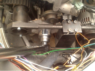
I also fitted the remote sensor housing. It comes with 50cm of braided hose to give lots of placement options, even so it's getting really crowded on that side of the engine bay. I eventually found a spot on the driver's footwell bulkhead along with what seems like everything else in the world:
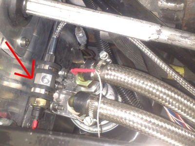
Here, I've plugged the pressure switch in (bottom), the empty port at the top is for the pressure sensor. It's held on with two P clips bolted through the bulkhead. Unfortunatley, this means that it isn't earthed, which is a bit of a pain since both these sensors rely on the body being earthed. So I had to drill and tap an extra hole in the housing to bolt an earthing wire to. Hope it doesn't leak!
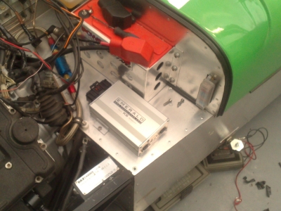
ECU
The car's brain arrived from Emerald in good time. It fitted in the spot I'd left for it on the battery shelf nicely:
With it in position, I started wiring up the power supply so that I can connect the PC to it. One thing to note is that, although it comes with a communications lead, it's for a serial port, which many modern laptops do not have - so a serial to usb adaptor is needed.
One thing I learned from the instruction manual is that it's best to run a "clean" power supply to the ECU, and run the power to the coils and injectors via a relay. This is because noise from the firing coils and injectors can cause the power supply to fluctuate, and that can affect the ECU if the supply is shared. So I did some rewiring to add this relay, in the process moving all of the main ignition wires from the dashboard switch to the relay. The switch now simply activates the relay, which will be a good thing anyway as it keeps all the high current stuff away from the dash.
Then I could power up the ecu and succesfully connected the PC to it. Another bit of the car comes alive...
From there I've been wiring in the injectors, coils, and various sensors. I thought that this was going to be a horribly complex job but it's actually looking fairly straightforwards, and should only take a few evenings.
One thing I am doing with the wiring is leaving everything unbundled and unwrapped - every time I've wrapped up a piece of loom, I've ended up having to strip it down to add or remove wires, so I'm going to leave it all until everything works, then go back and make it all neat.
So as things stand, I need the tensioning tool, still; apart from that things are forging ahead. Gauges will be the next thing, then all of the wiring should be complete.
20 June 2013
Timing, Finally
At last the tensioning tool arrived. Hurrah! I rushed to do the belt but rapidly came to the conclusion that it didn't really fit. Not the tool's fault, it's because of the modified water outlet I'm using which gets right in the way. I could sort of wiggle it in, but it wasn't quite right. This eventually lead to another belt slip and loss of cam timing, again.
I was so cross.
Soooo, I retimed the cams, for the third time, and modified the tool so that the weight hung below the arm. To do this, I just drilled and tapped some holes in the weight and bolted a plate on:
That, at last, worked. After two itterations of the tensioning procedure it was finally right. Now all I had to do was go back and fine-tune the cam timing, using the vernier cams. I would say that these are essential with aftermarket cams, there's no way you can get them set accurately just by adjusting the pullies on the cam tapers. However with them it's pretty quick to do. One of the exhausts was a long way off and needed resetting on the taper, the rest were within a few degrees and just needed a slight tweak of the verniers.
And that meant that, finally, I could reattach all of the coolant hoses, put the cam covers on and start building the intake tract up. But before I did, I figured that I should check that the oil pump was working. With the plugs still out, I gingerly connected the electrics and pressed the starter. It turned over without incident, which was nice. I mean I'd turned it over by hand any number of times, but you're never quite sure...
I left the oil pressure gauge out of it's housing, so that I could see when oil had reached that far. It took quite a lot of cranking, I guess filling up the filter and everything. I kept the cams well oiled by squirting assembly lube on them manually while turning it over. I could hear the pump gurgling, but no oil was apearing. So I removed the top cover for the pump driveshaft and poured a load of oil down there:
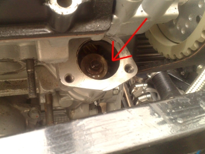
Soon after I had oil pumping out of the pressure gauge hole, and it started seeping out of the tappets as they pumped up. Success! I don't know if pouring the oil down the pump helped it prime, or if it just took a while, but either way, oil was pumped. I didn't even mind cleaning up the mess where it had overflowed.
On with the gaskets, and a final look at the cams for some years(hopefully!)