Wiring - Engine and Dash
20 June 2013
So onto wiring in the ECU and gauges, which are the last bits to do. I had a massive online shopping session and bought a whole load of stuff, largely small things which I needed (inlet gaskets, new screws for the throttle butterfly, various jubliee clips and the likes), but also a nice, shiny and expensive set of Stack gauges which are currently still in their packaging. So no pics, yet. Along with the tacho I've bought oil temp, oil pressure, water temp, and fuel. Along with a few lights and switches I bought at Stoneleigh, that's everything I need for the dash.
Alternator
I've also ordered a fan belt; these come in standard sizes, and after measuring I need a "K" section, 7 rib belt of between 83.5 and 86 cm. The K845 size is the one which is the closest match.
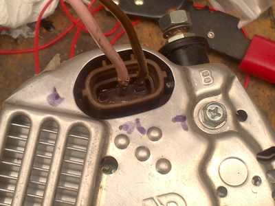
Having looked high and low for a connector plug for the alternator, I gave up. Several hours online only turned up something which was probably right, for getting on for 40 quid! For a plug! Popular though these alternators are, apparently nobody stocks the plugs.
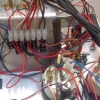
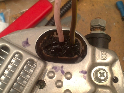
The pins are the same size as the ones on the ECU, so I've gone with two of the ECU connectors, soldered onto the pins for good measure, and then filled the plug with silicone to stop anything shorting or falling off:
From what I've read, the "P" connection gives a reference voltage which helps the alternator do some magic, but is not actually needed; so I've left it out which seems to be the done thing. I'll find out soon I guess...
ECU
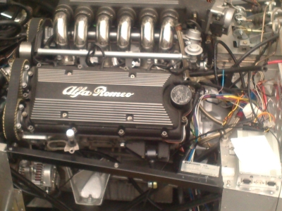
Before that though, I've been getting on with the ECU wiring. At the time of writing it's virtually done, just the IACV (Idle Air Control Valve) to go. Mostly it's been straightforwards, with a just couple of queries emailed to Emerald. One minor problem is that the ECU is set up to run external amplifiers for the coils, whereas I need it to run the coils directly, but they've sent me instructions on how to change it. Other than that, the only issue is the crank and cam sensors. I can't find any way that it's possible to tell which way around they are wired - just that it's important they are the right way around! The advice seems to be "try it and if it doesn't work, swap them around". I'm ok with that, but it's complicated because they share an earth wire; so I've 4 wires, running to 3 pins on the ecu, and I don't know which is which! So that's a few combinations. I've made up a temporary fly lead from the ECU into a normal screw terminal block, so that I can swap things around easily, and will crimp the pins on for good when I've worked out which goes where.
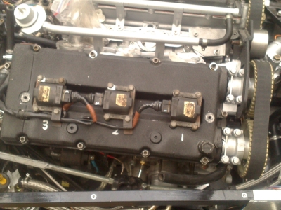
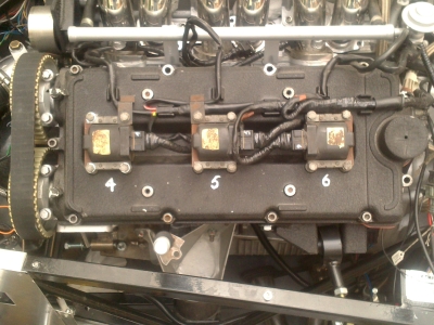
I've clipped all the coil and injector looms into place on the cam covers ready to go:
So it's getting close; once I've got the gauges mounted and wired in, I need to attach the fuel pipes to the fuel rail, stick a set of injectors in, refit the exhausts and it should be ready to start. Exciting times!
4th July 2013
Well due to a cock-up with paypal I've had a delay on my fan belt and a few other bits, fortunately I've had plenty else to do. Most of which has been laying out the dash, a job I've been looking forwards to since the begining. But before that...
Chapter 852: In which we tell of a ham-fisted Oaf with a torque wrench
I was cleaning out under the car and noticed a bolt head. I picked it up and the red line on it was an immediate giveaway - it was one of the propshaft bolt heads, sheared off!
Naturally I cursed, then removed the tunnel to see what had happened. The head of one of the bolts had indeed sheared off:
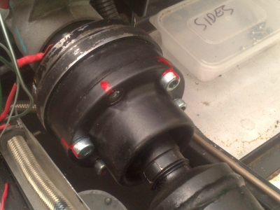
Now this was rather worrying; these are 12.9 grade bolts so should be very strong, and it's in about the last place I want any failures.
So I went back to check what I'd done; sometimes a build log is very handy! And what I'd done is use the torque figures for the ford end (4 M8 bolts) on the honda end (6 m8 bolts). Now I don't know what the ford bolts are made of, but the torque given in the Haynes manual is 57-67NM. The maximum torque for an M8 12.9 grade fastener (from various places on the internet), seems to be around 45NM. Ooops.
So as a wise man used to be fond of saying, "don't assume, check". I've ordered a new set of bolts since these are no doubt all damaged. I'm very pleased to have found this out now, rather than in use - even if it didn't break anything it would have been much more of a pain to sort out once all the seats are bolted in and the dashboard is on etc.
Dashboard
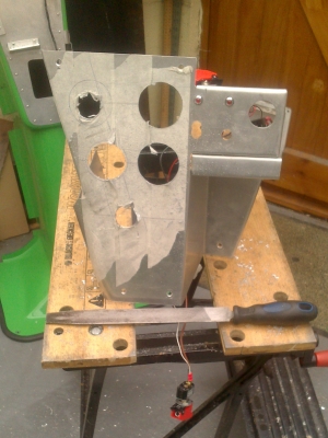
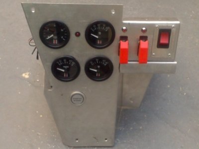
I'd planned the dash layout ages ago, using paint shop to mock up different layouts. I spent a bit of time revisiting these now that I had everything in front of me, made a couple of tweaks, and bashed on. The gauges are easy to fit, just cut a big 'ole and they mount from the rear (fnaaaar).
 Not done any of this for a while...
...and thence to the wiring. The standard loom just has a whole load of individual connectors to plug right into the back of each component, and a whole load of stuff which I don't need/need to change. To make things more manageable, I wanted a few multiconnectors between the dash and the rest of the wiring. So I've dealt with most of the complexity on the back of the dash, with ordinary screw terminal connector blocks, and just taken off two connectors for the middle bit, and one for the right-hand panel. Took a bit of thought but well worth it. As with everything else, I'm not going to wrap or tie anything down until it's all tested and working, so it's still a bit messy at the mo - but much easier to debug:
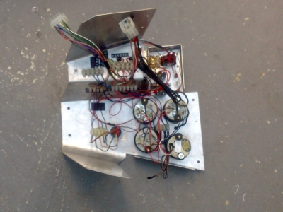
the eagle-eyed might notice that I've moved the start button, it was a bit hidden behind the indicator stalk where it was previously, so I've swapped it with the hazard switch.
Then it just remained to test it all out. Aside from an initial short circuit due to what seems to be a very odd design of hazard switch (probably just my lack of experience though), everything worked! Oh, except my brake light test switch where the switch I bought just doesn't work at all. But the circuit is fine. (I'm using a separate momentary switch, rather than a microswitch on the handbrake, because my handbrake mechanism didn't leave room for one - and you need to be able to test the light for IVA).
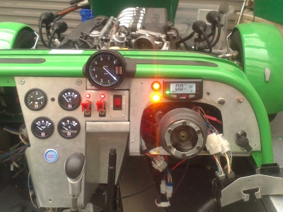
Here's the obligatory "all lit up" shot. It's got that "cold war aircraft" look I was aiming for. It all has to come apart for final finishing, labels making, covering, polishing etc so all the wonky bits are only temporary. But this will do for getting everthing working.
Next up, the last bit on the ecu wiring, injectors and all the little bits that need tidying up before I press the big "Go" button.