Front Lights
22nd February 2013
This is another of those areas which really has a fundamental effect on the look of the car, and is something I've been thinking about since the begining. In the begining, the low, rectangular lights was one of the things I liked about the Rush, never beeing keen on the more "classic" upright round ones as seen on Caterhams and Westies.
These days though, the rectangular units (which were originally from a 2CV of all things, though these days are Hella units) are maybe getting a bit long in the tooth, and there are all sorts of other options available. I'd long had my eye on using paired projector units, after seeing the look on SDR V-Storms (below, left) and Nigel Dean's "Raptor" v8 Rush (right)

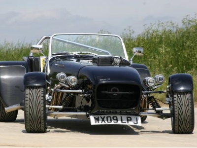
This kind of very modern look does seem to split opinion amongst kit builders, but personally I love it, and this is my car :).
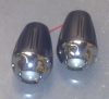
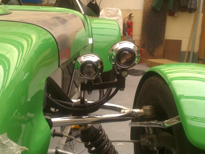
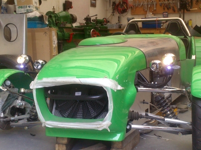
So I invested in a set of Photon projector headlamps, 2 pairs of dipped and mains. That was the easy bit:

Then you get onto indicators and sidelights. Here, the IVA requirements start being fun. Both indicators and sidelights must be positioned so that they are visible 45 degrees inwards, and 45 degrees outwards, and 5 degrees below the vertical. They must also be within 400mm of the outside edge of the car. This puts them in a space squarely between the body and the wheels; however, in this position the inward visibility becomes quite tricky as the nose gets in the way. The V-Storm gets away with it because, being mid-engined, the nose is much thinner and lower.
So the official Dax solution is the oft-quoted "SVA bars" (as they were introduced for that test). These are pretty hefty bits of tube which attach to the suspension mounts, and run along in front of the wheels, to which you mount the side/indicator units:
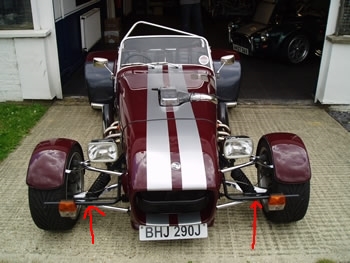
Now if you search for images of Rushes (including the one above), you'll notice that most do not have these bars - they have a tendency to "fall off" after the test and be replaced with something nicer. Smaller, stalk lights attached directly to the nosecone seem to be the preferred way of doing things.
I had a couple of problems with this - firstly, I didn't want to attach anything to the nosecone, otherwise I'll have wires to disconnect every time I take the bonnet off. Secondly, I rather like the idea of having my indicators highly visible, booring I know! So I thouhght I'd see if I could come up with something that would meet the test requirements and not look completely gash/weigh a ton.
Yeah, not easy! Obviously, or Dax would have done it I guess. There are plenty of lights available, but nothing seems to be quite right. Matching indicator and sidelights are hard to come by, unless you want 70mm BMC-look ones, which would look ridiculous next to my small headlights. Small sidelight led units I could find (as used by Mr. Dean above), but no matching indicator ones. You can get combined indicator/white light units, but they are either HUGE or only have one of the lights on at once. I don't know what is used on the V-Storm, I'm assuming a combined affair but I've been unable to find out anywhere. Indicators on stalks are plentiful in the motorbike market, but no matching sidelights.
Ultimately, it's a case of take the plunge, buy some, and see if they can be made to fit. So that's what I did. I've tried a number of different ideas, and I think number 4 (or maybe it's 5, I've lost track) is looking like it might work. Meeting the visiblity requirements and ending up with something that looks good (or even acceptable) is quite a challenge.
First few ideas, indicators and sidelights below the headlamps, outer headlamp lower than the inner. I was planning to use an LED strip in the bar with holes in to form the sidelight:
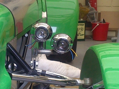
Measuring the angles of visibility: This is quite hard as there's no straight reference edges. So I took a line down the centre of the car, which is easy enough to judge, then used this to take another straight line down the side and through the indicator. Then I could set up a perpendicular, and get what should be a fairly accurate 45 degree inward angle:
All of the above were a no-go, which was a shame as it was quite a nice, simple design
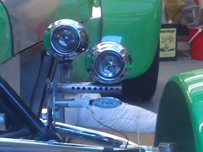
So then you start thinking, maybe the indicators and sides could go above the headlight, if I swap the led strip sidelight for a small button job. And indeed they can, and meet the visibility requirements. Looks wise, however...perhaps a bit wacky?
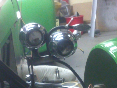
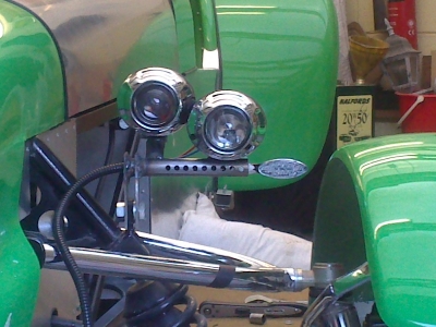
So current leading idea is to put the outer lamp higher and slightly forwards of the other, raise the whole lot a little, and put the indicators underneath the headlight. The spacing's a bit off here as it's a very rough mock up, but looks like it could work:
Tricky business! On the plus side, I'm getting lots of welding and general fabrication practice.
April 2013
Much fabrication has ensued, and I'm finally in possesion of a pair of light brackets. As usual, this has been a journey of trial, error, more error, throwing it all away and starting again, and finally, success. Making them out of tube has proved to be quite tricky, as getting the cut outs right to join the tubes at angles is very difficult by hand. I worked out where the sidelight needed to be for visibility, marked that position by building pointers out of aluminium sheet, taped to various bits of the car, then built the bracket up to that position.
A mistake I made early on was thinking that I could just fabricate it with the correct alignment for the light beams. But, even if the IVA manual gave you all the information you need to measure the beam pattern (it doesn't), getting this spot on would be a bit beyond my skills I think. So I had to make adjusters for each light which would allow it to pivot both horizontally and vertically. Below are all the pieces prior to full welding, finishing and painting:
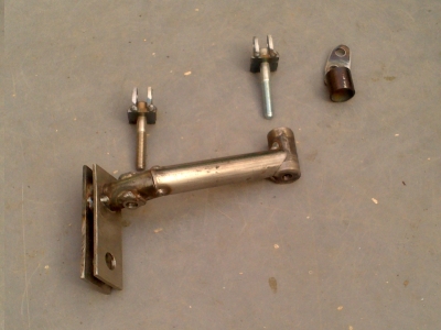
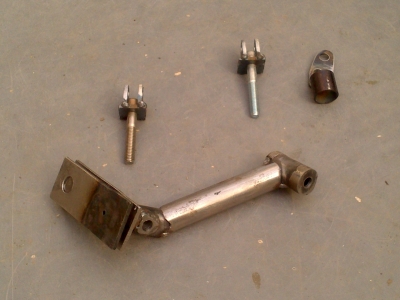
The ancilliary lights are 28mm button LEDs for the sidelights, and some generic motorbike LED indicators.
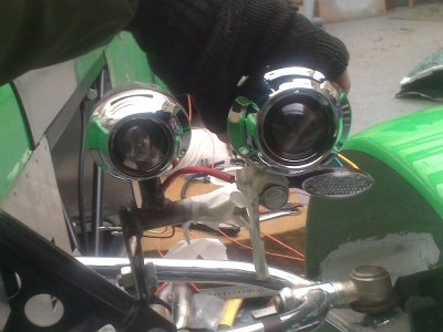
That sorted out mounting the light units; the final job is wiring them in. This wasn't entirely straightforwards as the Dax loom is made for the standard single light units, and also has no connectors, which would make removing the lights in future a pain. So I unwrapped yet more of the loom, made up some longer wires for each side, and put a 6-way connector on the ends so that I can unplug the whole light assembly on each side, should I need to. There was also a minor problem where the switch from dips to main turned off the dips - checking against both our road cars, the dips stay on when on main beam, which sounds sensible. So I had to add an extra relay and bit of cable in the interior loom to handle that.
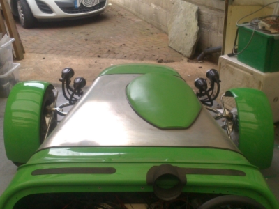
The one downside of the Photon lights is that the wires come out of the back of the unit, rather than out of the bottom. This is because they are designed for motorbikes. So your choices are, fold the wires back underneath the unit and try to hide them, or make a feature of them. I went for the latter, using unslit convoluted sleeving. The wires go into the back of each light through a large rubber plug, I simply cut a larger hole in this and sealed it up with plenty of black silicone. I was going for a kind of sci fi/utilitarian look, and I'm very pleased with how it's turned out. Likely to divide opinion, but there's only one I care about :)
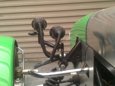

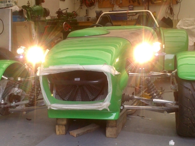
The main beams seem suitably dazzling, not sure about the dips but I guess I'll find out. The small LED sidelights are surprisingly bright, and the indicator position is very good from a visibility point of view.
Job jobbed, and (hopefully) all IVA compliant without any dodges or bits falling off after the test.
Front Wings
The final lights to be done are the side repeaters. These are infamously hard to position on seven-type cars since the IVA requirements came in. The problem is that each light has to be visible from behind (actually, 5 degrees outwards from directly behind), and 5 degrees below the vertical. On a seven, the large rear arch means that it is impossible to achieve this if the repeater is attached to the main bodywork. The normal solutions to this are to attach the repeater to the front or rear wheel arches. Or in Dax's case, via an obviously-only-for-the-test long pole which attaches to the bodywork and sticks out by about a yard. Yeah, no thanks.
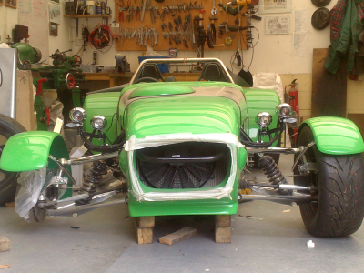
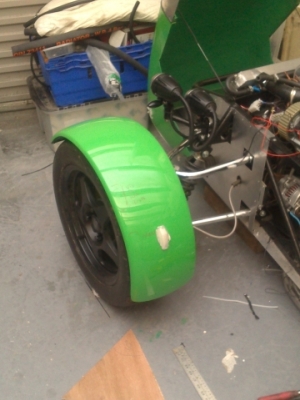
So the front wings look like the best place; which meant that I'd better get around to actually sticking them on!
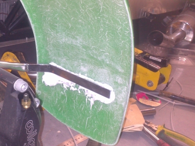
This is done by wurth - lots and lots of wurth. This tends to make people think twice, but then it works and I've never heard of one comming off.
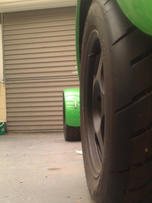
So it's not too hard a job - tape a few bits of wood to the tyre to act as spacers, wurth on the wing stays, on with the wing and hold it on with cable ties until set. Then you take the wheel off, and encase the wing stay with a load more wurth:

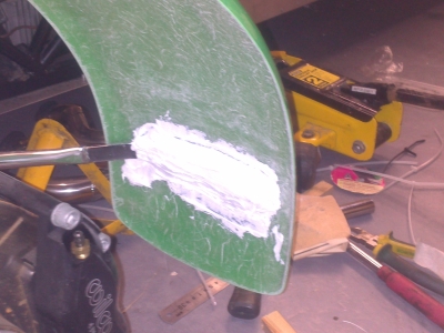
It took a few days for the wurth to harden off because of the cold weather, but once it does, it easily passes the "sit test". Finally, I gave the underside of the wing a coat of dark green gloss as I'd done for all the rest of the GRP bits. So now it's time for the dreaded side repeaters...
An Aside - Water pump and other parts...
I finally got bored of waiting for a pump via the main dealer and looked into reconditioning. A quick google and phone conversation and I found somewhere that could recondition the pump in a day or two, for just over half the price of a new one. So I cancelled the order for the new one and did that, they turned it around in 4 days and it's come back good as new.
I seem to generally be just falling behind the cut off date at which parts start disappearing - I'm now trying to find a timing belt kit, last year I found a few for sale on ebay and the likes, now they're nowhere to be found. Obviously I didn't realise when I bought the donor that this engine was a short lived model or I'd have waited for a newer one. What I might need to do when I finish the build is buy up a late model engine (which are now as cheap as the one I bought - a few years makes a big difference) and a set of spare rings and bearings, so that I'm sorted for the next 20 years or so.
Side Repeaters
26th April 2013
With the wheel arches on, I started looking at mounting the repeaters.
The problem on a Dax is that the front wings are very shallow - which looks very cool but unfortunately means that there's no side height to stick a light into. I'd bought some 28mm button indicators (same type as I've used for the sidelights) hoping to do this, but there just isn't the clearance between the wing and the tyre. I even went as far as taking a fiberglass mold of a section of arch, and making a piece so that I could try various shaped cutouts etc - but to no avail.
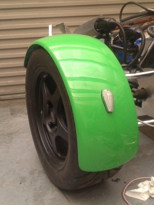
So I bought some surface mount indicator lights. A bit of a play around with the angles suggested that I could fit them to the rear of the wheel arch:
All good, I thought - looks good, and really good visibility from all the specified angles. BUT I hadn't seen anyone else put them there; so before I drilled any holes in my front wings, I thought I'd check with other people in case there was something I missed. See threads on Locostbuilders.co.uk and the Dax Forum.
The obvious thing which came up was a) that there is a great deal of confusion, generally about what the manual says or means; and b) that it wasn't clear if the repeaters had to be visible when the wheels were at full lock - something I hadn't considered.
Since nobody actually seemed to know (despite there being plenty of opinions), I figured I'd just go straight to the source and ask VOSA. A mere 11 days later came the reply:
" We have now received an answer back in respect to your enquiry and it has been confirmed that the angles are checked "with the wheels in the straight ahead position". Hope this now helps you finalise the positioning of your lights."
I figured that this had to be the case, looking at Westfields and Caterhams and several others which fit them on the side of the arches, which will be invisible from the rear when on full lock. But it's good to have it from the horse's mouth. I will make sure to take a copy of the email to IVA, just in case.
Actually fitting the lights then was pretty easy. They are surface mount with an adhesive pad, I removed that and bonded them on with wurth. Then a single hole drilled for the cable. I covered this with convoluted sleeving, sealed the end, then wurthed it alongh the underside of the wheel arch down to the stay.
From there, it's cable tied along the stay, down to the bottom whisbone where there's a handy niche under the strengthening gusset. I needed to drill a small hole in the gusset to get a tie through. From above, you can barely see any evidence of the cable:
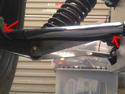
Visibility from 5 degrees out, and 5 degrees below vertical is fine in this position: