Cooling System
19th January 2013
Happy new year to anyone still reading. A look back tells me that it's 4 years, 4 months since I started stripping down the donor car. I'd originally expected 2 to 2 1/2 for the build which shows how much I knew! Still, at least I'm getting my money's worth I suppose.
So as per the plan, I've spent January (mostly) trying to sort out the cooling system. It's a bit of a short month, what with new year, and a holiday, and it took me a while to get back into the swing of things after really not touching the car for a month - December being mostly a write-off because of the dreaded Christmas.
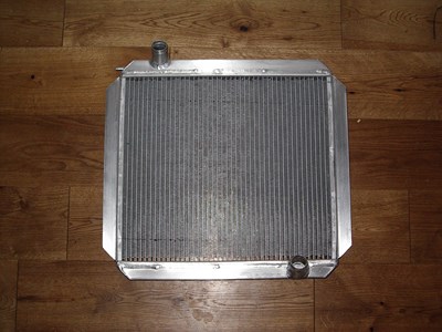
My radiator arrived from Dax, it's smaller than I imagined, but then that's the size of the space in the chassis. Nice and deep, and lightweight too. I also ordered a fan kit - you can spend anything from 25 quid for an ebay special to several hundred for a motorsport item. I went with a Pacet 14" kit in the end, which at around £145 are certainly not a cheap option, but several other builders have used them succesfully. 25 quid is tempting, but there must be something missing for that price difference...and one breakdown and replacement work will quickly burn up the difference.
Now everything you read will tell you that it's best to have the fan behind the radiator - it's easier to pull air through something than push it. Having the fan in front also disrupts the airflow before it gets to the radiator core. That said, most Rushes I've seen have the fan in front. But I thought I'd try a rear-mounting (fnaar).
This means building some brackets to hold the radiator out in space in front of the chassis rails - conceptually easy, but a bit hard in practice as you can't really clamp or otherwise hold it in position to measure anything. So a bit of a faff, but I got there and tack-welded a couple of brackets on so that I could get the thing into position. I also had to trim the mounting flanges of the radiator to get it to fit, because the chassis narrows as it goes forwards.
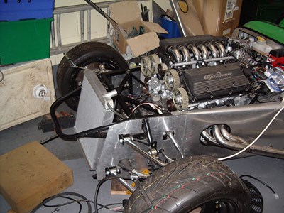
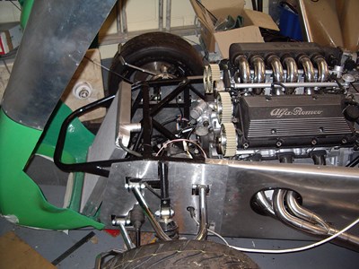
The first attempt looked pretty good - room for the fan behind, and even better, it stood the radiator up more vertically which could only help airflow and cooling:
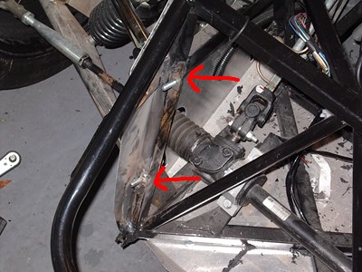
I was all ready to weld it up properly when I realised that the radiator inlet was waaaaaay above the outlet on the engine - which would mean that air could get trapped in the top of the hose, and limit the water flow. I only noticed, I think, because I'd read in Des Hammil's Rover V8 tuning book about just such a problem on one of the range rovers (HSE 4.6 I think, but don't quote me). This lead to a chronic overheating problem and meant that most of the engines on that model failed at some point during their lives.
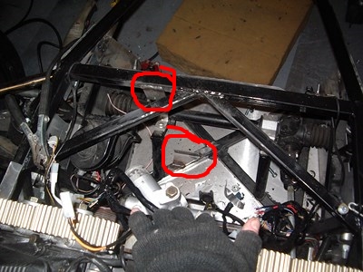
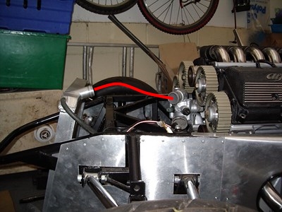 The red line shows where the hose would go, leaving a nice big loop at the top for air to collect in.
I could cure this by putting in a radiator cap at the high point, so that air could be let out when filling, but that sounded like something I could do without. So on to plan B; leave the radiator at the normal "tilted back" angle, but just space it forwards. So, remove old brackets, make new ones, tack weld on, and it looked much better.
Great, thought I, job done. But alas, although the rad was now in a good position compared to the engine, and had space for the fan, it fouled on the bonnet when I tried to remove it. So I was really looking at chopping part of the bottom lip of the bonnet away...and I decided that, on balance, I'd rather just have the fan in front of the radiator like everyone else did. So a couple of wasted nights there, but never mind. For anyone else doing this, I would guess that on a normal car engined rush, with the standard car nosecone and bonnet (where the nosecone is fixed and the bonnet lifts off), moving the radiator forwards like this would be fine - it only fouled when my one piece bonnet/nosecone was tilted forwards and lifted to get it off my home-made hinges.
So, I was back to mounting the radiator where it was "supposed" to go, up against two crossed chassis members. No problems there, but I also had to think about the oil cooler. I'd intended to stick it on the front of the radiator, which again is the "done thing", but with the radiator in position, there's simply no room to get the oil hoses in front of it - it fills the space completely. The only way would be to run them over the top, but that seemed a bad idea, again because of the potential for air to collect, and also because it's all adding more work for the engine to do to pump the oil.
So there was no other option but to mount the oil cooler behind the radiator. This will limit its efficiency, but thinking back to the donor car, the cooler was stuffed behind some bodywork somewhere off to the side, so I can't see it would be any worse. Given that people run 4.6L V8s with these radiators and no oil cooler, I can't see that cooling is going to be that marginal anyway.
Of course, this meant that I had to sort it out before I could put the radiator on, just so I could get to it. There's plenty of space between the radiator and engine, so it was easy enough to find a gap for the cooler to go into. I made up a couple of brackets from 2mm mild steel, welded them onto the chassis, a lick of paint and off we go. Note that it's mounted vertically, which is the same as in the donor car. From everything I've found on the internet, it doesn't really matter which way it goes.
 Left - new brackets welded on to chassis. Right - oil cooler mounted.
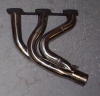
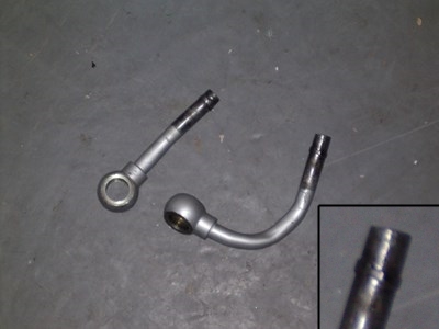
The cooler's connected with braided hose and push-fit connectors, same as I did for the filter. It connects to the oil take off pipes which I modified previously. When it came to connect the hoses, I was a bit worried about the lack of any flare or other knobbles to prevent the hose pulling off (even though it will be clipped). The thick steel looks far too strong to flare with my flaring kit, so I ran a bead of weld around the end of each tube. Then ground it down until I had a ridge, about 1mm high all the way around. Picture isn't great, unfortunately:
The build manual says to mount the radiator with self-tappers into the chassis (it says to mount most things with self-tappers into the chassis). But the radiator flange doesn't actually overlap that much of the chassis, and the fewer holes the better as far as I'm concerned, so a bit of bracketary is required. At the bottom, I've just welded a bolt to the chassis - at the top, a bracket with a hole for a bolt to go through.
Then simply bolt the radiator on, and mount the fan. The fan kit comes with "quickmounts", which are basically posh cable ties and spacers. They poke through the radiator matrix and are tightened up with a plastic ratchet bolt on the rear side. Nice and easy, for once. I've mounted the fan to one side, just to leave a bit less obstruction on the side where the oil cooler is.
To control the fan, there's a thermostatic switch - I've not got there yet, but this will be mounted on the top chassis rail, just next to the radiator top hose.
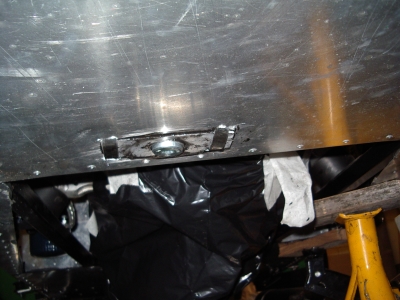
Something which is a concern is going to be draining it. With my natty aluminium flat bottom underneath the nosecone section, I'll not be able to pull the bottom hose connection as there will be no-where for the water to go! So I'll either have to find some sort of drain valve and have a bit of hose to take the water somewhere else, or start chopping holes in the aluminium. Bum.
In the meantime, I've ordered an expansion tank. When I've fitted that somewhere, I'll be able to order a set of hoses and connect it all together.
Engine Stabiliser Rod
Another concern, which has been on my mind for ages, is the closeness of the cam pullies to the chassis. I may have gone on about it before...
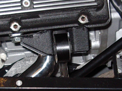
Anyway, it's about 10mm, which aint a lot. As I mentioned some time ago,we had a look at Frank's rather fine v8 Rush at the Donnington Show, while he rev'd it to see how far the engine moved on its mounts. Answer - about 10mm. Urgggh. Might be fine, but it's gonna be awful expensive if it isn't! There's also the issue that the gearbox mounts will have very little movement in them, so any twisting force is going to be putting a strain on the gearbox casing, which doesn't sound nice.In the donor, the engine has a stabilising rod attached to the top bracket:
I had to remove this because it was going to be sticking out of the bonnet. So I needed to find another mounting point. A good couple of "staring at" sessions later, and I settled two unused M10 bolt holes on the passenger side head - I guess they're for lifting or mounting on an engine stand. This would let me run a rod down to the bottom chassis rail; not ideal because it puts a bending load in the middle of a rail, but then it's not going to be a very large load, it just has to resist the side-to-side torque reaction of the engine. It seemed like the neatest possibility.
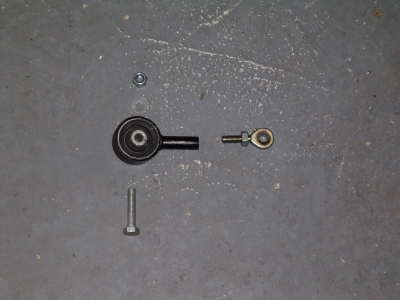
Unfortunately, I'd thrown out the original stabiliser because I didn't think I could use it. But trying to find a big rubber bushing to take radial loads is rather difficult; in the end, I had to buy a spare stabiliser rod from ebay. I went with one from a diesel though, because it had two of the same bushings, one on each end, just in case I cocked up...
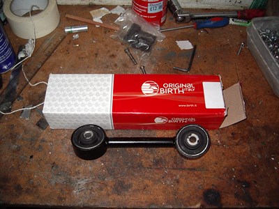
Now, as it stands, this isn't long enough. So I needed to extend it. It feels as if one of the bushings will give all the movement I want to allow, so I'll cut the rod in two, and just use one of the bushings. I'll extend the solid rod, and put an M10 rose joint on the end, which will fix to a bracket on the chassis.
I had some mild steel tubing lying around which was exactly the same size as the existing rod, and will be plenty strong enough. I wasn't sure if just butt-welding it to the solid rod would be very strong, so I did a test piece, welding a length of the tube to a spare bit of solid bar. I then clamped the bar in the vice, and beat the tube with a large hammer. I was pleased to see that the solid bar bent, while the weld held solid - so I'll call that "strong enough".
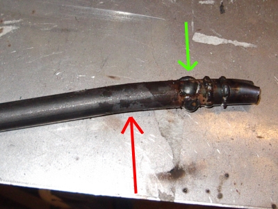 Red Arrow - bar was clamped here and has bent at this point. Green Arrow - point where the tube is welded on. No bending here! The other welds were old practice runs.
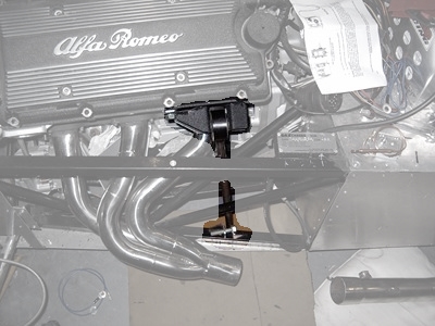
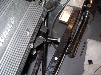
Things were looking good, so I cut the rod, welded on a length of tube, and made up a bracket to fit to the cylinder head, which would take the bushing. I then made two smaller brackets which will be welded onto the chassis rail. At the time of writing, I'm awaiting the arrival of the rose joint, so I can't quite finish things off yet. You can see the idea though:
And completely off-topic, I notice that the nice bods at Microsoft have made the new version of Internet Explorer (IE 10) work differently to everything else, again. So if you're getting double scrollbars at the right hand of the page, apologies, I'll sort it later. Why oh why oh why can't they follow standards like everyone else, or at least, keep their random non-standard behaviour the same between versions? Grrrrrrr. They've made the font look crap as well.
22nd Feb 2013
Well I seem to be getting nowhere fast at the moment. Everything I order seems to come wrong, or turn out to be unavailable, or I ordered the wrong size. Anyhoo...
I finished the stabiliser. I decided that the design above, with it bolting down to the bottom chassis rail, wasn't going to be at the correct angle. So I decided in the end to do it to the top chassis rail instead. This makes it much shorter, so I didn't actually end up having to extend the rod at all. Instead, I drilled and tapped it to M10 and put a rose joint directly into it. A simple bracket welded to the underside of the chassis rail and that was that:
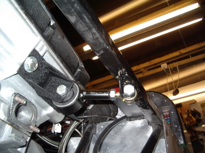
Pretty neat, and should stop any "innapropriate contact".
Oh dear oh dear oh dear. Pretty neat, yes, but the rear bolt holding the bracket on, turns out to be the hole for the oil pressure sensor! So this all had to be scrapped, and I had to make a different one :(
... And then after making a different one, I realised that I could mount the sensor remotely, and I could go back to this idea after all! As you were...
Cooling System
I wired up the fan; it's designed to take a direct feed from the battery, and have the thermostat and fan inline, but the dax loom includes separate wires for the switch, and a relay for the fan, so it needed a bit of modification. The fan is reversible so that it can be made to pull or push air through the radiator. I've fitted it as a "pusher", which meant that the fan blades needed taking off, flipping over, and refitting. Simple, except that I had to buy a 3-leg puller to get the darned thing off the spindle. Another 5 minute job which ends up taking 4 days and costing 25 quid. You also need to connect the wires the other way around. Anyway, when all wired up, I can turn the thermostat down and on comes the fan. Seems to do a pretty good job too, a good airflow through the rad and oil cooler, and surprisingly, well, not quiet, but not nearly as noisy as I'd expected. Well worth checking, it's not unheard of for people to fit the blades / wires the wrong way round and end up with overheating problems.
So, on to the actual plumbing. By the magic of Paint.net, here's a diagram:
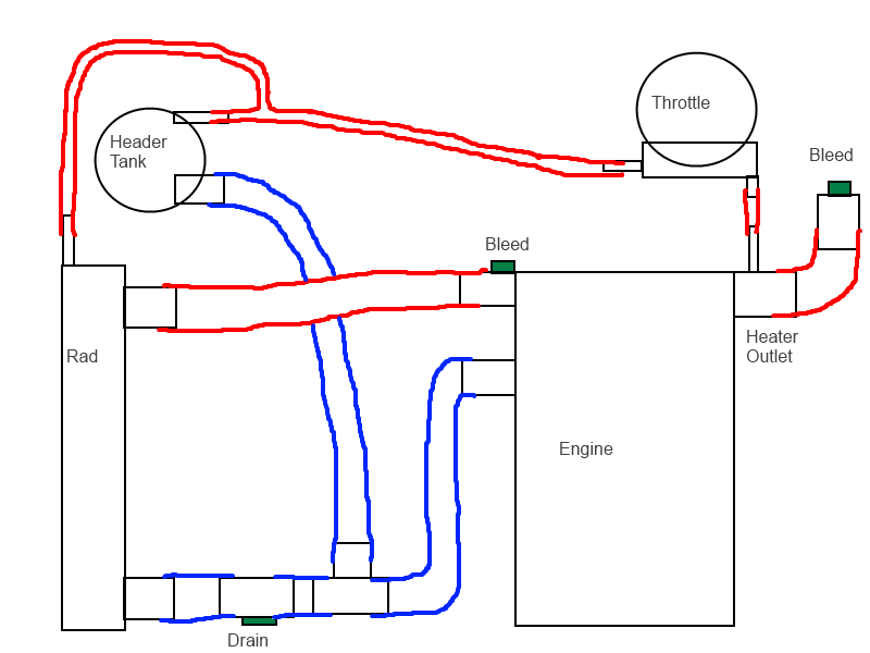
I wasn't sure about how the header tank was supposed to work until I did some research, but I think I've got it right. I'll be blanking off the heater outlet, and putting a bleed screw in there as it's (nearly) the highest point of the system. The header tank should really be at the highest point, which is how Alfa had it, so that any air bubbles gradually work their its way into the tank. Unfortunately, because the water flows through the throttle body (I guess prevents icing and helps cold starts - not sure if this will be useful to me or not, but I thought I'd keep it connected), this would mean having the tank high up on the scuttle - and there aint room (or won't be by the time I've fitted all the air ducting and stuff.). So I've put it at the front of the car, which due to the bonnet line, means that it's slightly lower. Hard to know if that'll matter, but given the small diameter (8mm) of the hoses concerned, I'd have thought that any airlocks should get pushed along the tube, rather than sitting there. Certainly small bubbles flow downwards in small-bore syphon tubing when I'm making homebrew :). There's also a take-off from the radiator to the header tank - this is to allow overflow as the water expands, and again to allow any bubbles to get out.
The outlet from the header tank goes into a t-piece on the bottom hose. In order to drain the system, I've used an "inline adaptor". This is a length of alloy pipe with an M22 hole tapped in, intended for the fitting of sensors. I've mounted it with the hole facing downwards, and a plain screw plug in.
So much for the design, what about the implementation?
Well, although technically not hard, it's tricky because to some extent, you need to have the various bits of pipework to hand to see how it might all fit. With a stockroom full of hoses and connectors it would be easy to put it together, but as it is, you have to order each piece. Then you find that it doesn't quite work, or there's a better layout, so you inevitably end up buying bits you don't end up using. I think I've got some ebay selling to do soon...
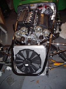
Header tank mounted above the rad - lots of room at the front here:
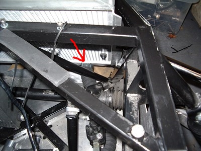
The bottom hose was a bit problematic. The outlet of the radiator is cleverly positioned just in front of a chassis member, necessitating either a couple of 90 degree bends, or what I used, some convoluted flexible hose. Because I've put a floor in the front section, access is very limited, and I didn't fancy having a series of joins at the front which could leak. That said, 90 degree bends may be the best way, as it was a pig to thread the flexible hose in. But I got it there in the end, with much heaving and swearing: (Outlet arrowed)
This then curves around and is connected to my drain adaptor. I've added two large jubilee clips which go through the floor and around the hose to hold it all in place. I've bonded an extra ally plate onto the underside of the floor to give it all some more support. Drain is arrowed (1) below:
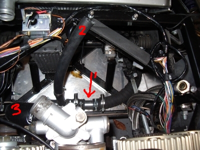
The hose comming upwards(2) is for the outlet from the header tank. To the left of the picture, there will be a right-angled bend sending the pipe upwards and onto the water pump inlet (3)
Picture of the drain from underneath. Not my best work, but I couldn't really think of a way other than jubilee clips. Should be very practical at least.
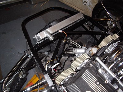
Not quite finished yet, but here's the top hose ready for trimming, and the thinner expansion hoses loosely in position. When it's all clipped in place, I'm hoping it should make quite a neat installation.

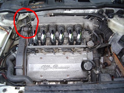
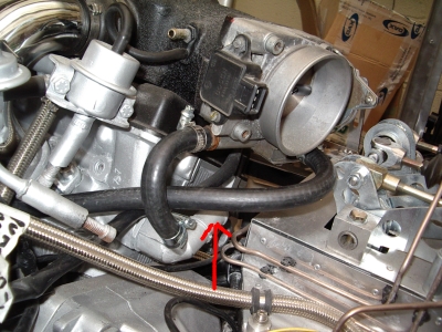
At the other end of the engine, is the heater outlet. This is the large pipe arrowed below - it's pointing away from us. A smaller pipe comes off the heater outlet and runs to the throttle. The return pipe then runs back down between the heads, to the expansion tank.
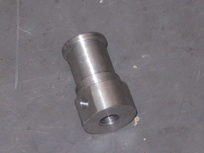
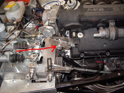
As mentioned above, I am blanking the heater outlet and putting in a bleed screw. I turned up a aluminium part for this, to take a 12mm bolt:
There wasn't anything really obvious to bolt it to, so I elected to fix it to the underside of my throttle cable bracket. It'll be easily accesible there, and not in the way of anything.
Waterpump
I've also been trying to get hold of a new waterpump. Now that's a faff. This engine seems to have been on the cusp of a change, and having tried several pattern suppliers, the ones in the parts catalogues don't seem to match the one I need. My one has a pronounced "n" shape to the left hand arm, whereas it seems that later engines have a flatter arm. Bizarrely though, all of the parts catalogues seem to list the new type as appropriate for the engine I have. I guess that mine was a short lived design, perhaps a hold-over from the 12v engines.
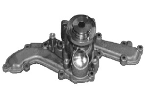
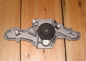 Left - the type of pump I have. Notice pronounced "n" shape on LH arm. Right - the later type, commonly (incorrectly) listed for this engine.
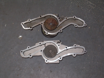 Comparison of the two types from the other side. Top - mine, Bottom, newer type. Notice the difference to the arm (here on the right)
So my last resort has been to go to a main dealer, who assures me that they can get one, on special order, with no ETA, for an eye-watering 180 pounds. Ouch. I'll do it though, as this one looks to be getting on a bit, and a new one should give me years of use. If I can't get a new one, or I do and it eventually wears out, there are various places which can recondition pumps (it's only a couple of seals and bearings after all), or I could convert to an electric pump. For now, I'll get it together using the old one and hope the new one arrives.