So Close, So Far Away...
09 August 2013
Well what an odd month. A pleasant holiday, a broken PC, a total catastrophe and filling in with a whole heap of odds and sods. It's felt like I'm in touching distance of the end, but at the same time, there still seems to be a mountain to climb. Summer is disappearing fast, and at this point I feel like I'll be happy if I'm ready for IVA by the end of the year, let alone get it on the road before winter. Where to begin?
Catastrophe
I'll start with this, because it happened first.
Long story short, but I finally got everything wired up. As I'd mentioned before, the ECU was set up to run external ignition modules, and I had to do some software changes to run the coils directly; I don't know if this had a bearing on what happened. But anyway, I had it all plugged in, and was working on a completely unrelated bit of wiring under the dashboard. I turned on the ignition to test it and after a few seconds smelt the unmistakeable smell of melting plastic. To my horror, the main earth from the ECU was suffering a full meltdown, so I ripped the leads from the battery and surveyed the damage.
 The first rule of electrics is...keep the magic smoke *inside* the wires. Oops.
The earth lead was toast of course, but nothing else seemed to have been touched. The ECU seemed at least partially fine, in that I could still power it up (having relaced the earth, and removed all other wires except power and earth first!) and connect the PC to it. But a series of tests showed that something was behaving very strangely. Specifically, turning off the ignition caused the radiator fan to come on. Some trial-and-error investigation showed that the ecu appeared to be earthing back through the fan relay when the power was removed, which was in turn flowing through the main power relay and keeping everything on. After a couple of nights of testing, it seemed clear - the ECU must be damaged :(
So I spoke to Emerald and sent it back for diagnosis. For two weeks I was expecting a very expensive bill, but when they rang, they said it was fixed under warranty and there was no charge apart from shipping. To say I was over the moon would be an understatement, what great service.
It arrived back the next day with a wiring diagram detailing a couple of changes to make, which I've now done. I don't know if I broke it by connecting it directly to the coils, or if there was something wrong with it to start with - but I gave them full details of what had happened so I can only assume that it wasn't entirely my fault. Hopefully then, what could have been a collosal and expensive disaster has had little ill effect.
Final Engine Bits
As it happened I've had plenty of other things to do while I was waiting, building a new PC after the motherboard died was one. On the car front there was a large number of small jobs to finish.
The sensors for my gauges were all M10x1 thread, and the bosses in the engine generally different. I found an adaptor for the water temp sensor:
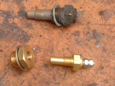
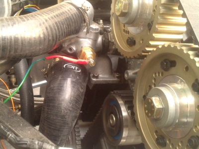 Top Left - original sensor. Bottom - adaptor and new sensor. Right - sensor in place.
That one was easy. For the oil temperature sensor, the usual thing is to fit it into a special sump plug adaptor. My custom sump has a normal M12 threaded bolt for the plug, but normal sump plugs (it turns out) have fine threads. So I couldn't find an adaptor to fit. In the end I made my own on the lathe, out of stainless. Shown below with the sensor in place:
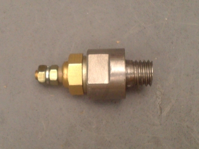
Easy, but rubbish. Despite trying a couple of designs for a sump-mounted sensor, it just never gives you a useful reading - the temperature at the bottom of the sump never gets much above 60 or 70 degrees, and takes ages to get there. Completely useless, basically. Eventually I replaced this with an inline housing in the oil line from the block to the filter, which works really well.
Getting the fuel pipes plumbed in and testing that the pump worked was a milestone. I put a gallon of fuel in the tank (which felt like things were getting very serious), temporarily hotwired the fuel relay (it's normally ecu-operated), and checked that fuel was being pumped. I wasn't sure how rapid a flow to expect, since the system runs under 40psi pressure, but it was quite managable with a jam jar.
A good steady flow, so it was time to connect the hoses up for real. And after hearing about more than one garage fire caused by electrical sparks and fuel vapour, one to a fellow Dax Rush owner, I was exceptionally careful to have all the doors open for ventilation, and to always remove the negative lead from the battery first. Dangerous stuff, petrol.
The connection from fuel lines to the fuel rail is just push on with jubilee clamps. I'd looked at getting annodised fuel line finishers which look like JIC fittings, but are actually hose clamps - but they looked a bit too obviously fake for my money. I'd rather be honest, if they're jubilee clamps, then why try to hide it? So I just went with rubber end caps to stop any fraying, and quality stainless clamps.
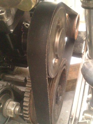
Then my fanbelt arrived, finally, after much faffing with Paypal. Happily, my measuring was right and it all fitted perfectly:
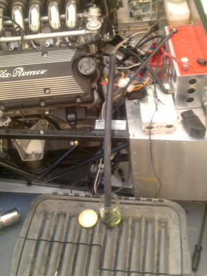
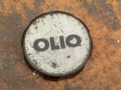
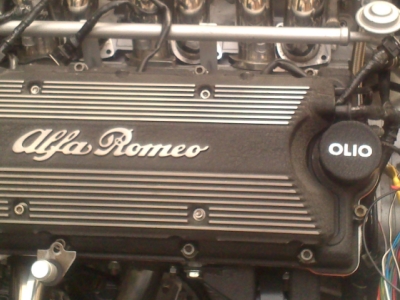
The oil cap that came with the car was broken, so I'd been on the lookout for a new one. The most sought-after are the older ones which say "Olio" rather than "Engine Oil", 'cos it's more exotic. They tend to fetch a premium price so I wasn't overly bothered about one, but as it happened, while browsing one night I saw one on US ebay for the same as a normal one. So for a few quid extra shipping, I thought I may as well.
These are getting on a bit now so it was a bit worn - so I painted it to match the rest of the engine. It works I think:
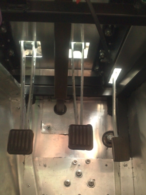
Another thing was the throttle cable. Finally it could be properly connected, it's been flopping around annoyingly for, well, a couple of years. Now that the brakes and clutch are all connected, I could get a better feel for how the pedals would all work. It was obvious that the throttle was a bit too high compared to the brakes, and heel-n-toe was not going to be possible. So I spent a morning fettling and adjusting to get it right. I had to reduce the diameter of the throttle pully by a couple of mm to increase the leverage, and modify the backstop I'd made so that I could push the throttle pedal further back. In the end, I could (just) get it into a position where I should be able to brake without hitting the throttle, and heel and toe, and hopefully the throttle will have enough movement to be easily adjustable. It's close though, there isn't much room in the footwell and not much leverage on the throttle pedal, even with my additional linkage. Worth taking the time to get right though.
Injectors
I'd known for ages that I'd be wanting a larger set of injectors - the general consensus is that the standard ones are pretty much flat out even in standard tune. This list of Bosch injectors confirmed that. The standard injector, part number 0-280-150-701, has an estimated output of 35.2hp at an 80% duty cycle (which is the recommended maximum); multiplied by 6 gives 211hp, rather close to the quoted maximum power for the engine of 210. So there isn't much more scope for increasing output with them.
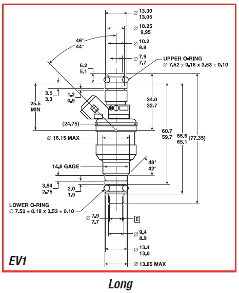
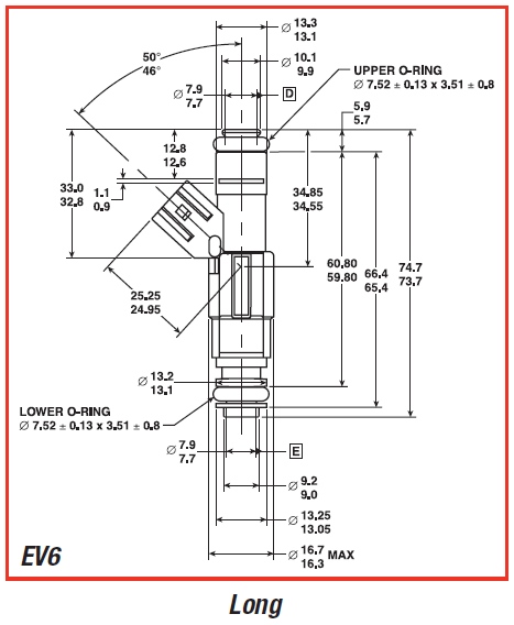
Injectors were a bit of a mystery to me, but a few nights reading revealed a few nuggets of information. First, the form factor (EV1, EV6, EV14, and others). This is the size and shape of the injector. The original ones are EV1. EV6 are a newer design, thinner, with an improved type of nozzle, BUT the height of the injector and diameter of the o-rings which connect to the fuel rail and head are the same. (So an EV6 will fit where an EV1 will, though the reverse might not be true as the EV1 is more bulky).
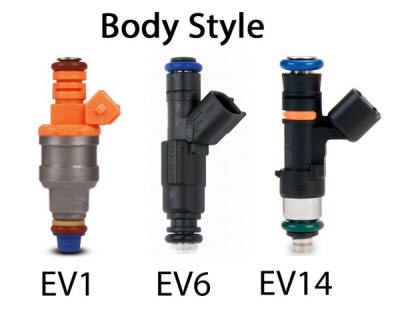 Image taken from http://www.americanmuscle.com/is-your-mustang-starving-for-fuel--79-13-.html
 Images taken from http://www.rmaperformance.com/tags/ev6/
So far, so good. Where it gets confusing is in the type of electrical connector. Older ones, such as the standard Alfa v6 injectors, usually have a junior power/minitimer connector which is square. The newer ones, generally, have an oval USCAR type. Because of this, you often see the form factor and connector referred to as the same thing - so some web pages will talk of an "EV6 connector". But it's not right - there are EV6 shape injectors with square minitimer connectors.
With that in mind, cue more research to find something with an EV1 or EV6 form factor, a minitimer connection, and with a bit higher rating, but not stupidly higher. Too big and you loose resolution at lower engine speeds/loads, and hence the engine wont run well except when accelerating hard.
I soon found out that the injector from the Volvo T5, Bosch number 0-280-155-766, is the popular choice. Rated at 350cc/min (standard ones are 224), that will give an estimated output of 51.2hp per injector at 80% duty cycle, or 307hp total - which should be plenty. Even better, these are quite widely available; I found a reconditioner selling tested ones at around a fifth of the price of new ones.
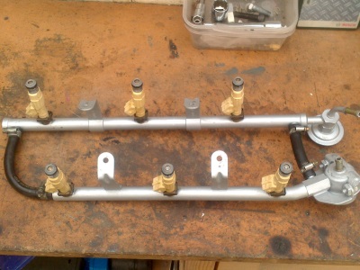
There was a slight cock up with the courier, meaning that they took a couple of weeks to arrive, but the seller sorted it out as well as could be expected. Below are shown the standard Alfa injector (left), with the Volvo one on the right:
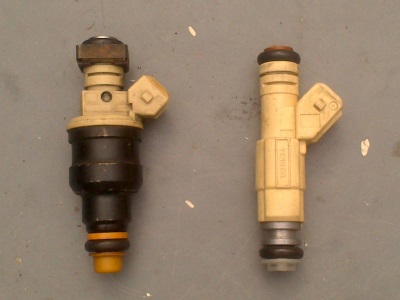
And fitted to the fuel rail below. Having tried both ways round, you want to fit the injectors into the rail, then fit the whole lot to the engine, rather than put the injector in the engine and then attach the rail.
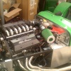
With them in, I could finally, finally, bolt on the inlet pipes and plenum, and connect all the wires. Easy enough work, though took a surprising amount of time, largely because I was trying to keep everything neat.
The only real gotcha are the inlet gaskets. These all look the same, but are actually handed, and two of the inlets need them putting on the opposite way up to the others. It's not completely obvious and easy to get one wrong. Ask me how I know...
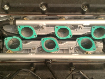
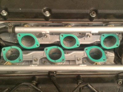 Left - WRONG! Cylinder 5 gasket is the wrong way up, notice the overlap. Right - er, Right. Note gaskets for cylinders 4 and 5 are the other way up from the rest.
With bigger injectors of course, the fueling map in the ecu will be wrong; it will be overfueling everywhere. Fortunately, the Emerald software comes with a convertor which lets you enter the old and new injector flow rates, and works everything out for you. Which is nice.
Other bits...
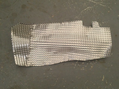
On the driver's side of the engine, there is now an awful lot of stuff packed in under the exhaust - oil lines, the starter motor, and all the wiring. I thought it wise to put a heat shield in before anything is started - I've had enough melted wires to last me for years.
I used some dual ply aluminium heat shield - not cheap at 20 quid a piece, but lightweight, rigid, and easy to form:
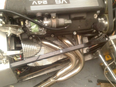

That done meant that I could finally put both exhausts on. I've elected to leave the side panels off at the moment, so I can get at everything and check for any leaks etc. Which does mean that I'll have to pull the exhausts at least partially off to get the panels on later, but I think it's the best thing to do. A shame because the manifolds bolts are a right pain to get at.
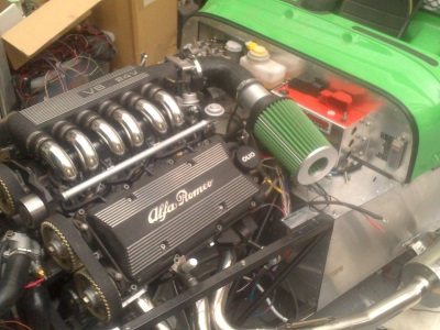
I also needed an air filter of course. It took a surprising amount of time to find one with the right neck size, with the right capacity. Eventually I went for a Green Filters cotton one, which had the added advantage of matching the colour of the car (though this was just a happy coincidence).
A bit of silicone hose and an aluminium joiner and in she goes:
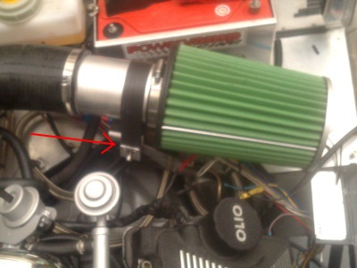
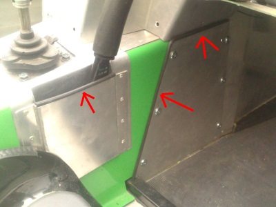
I made a bracket from stainless which bolts to the battery shelf to hold the filter up, over the fuel lines and wiring which are all trying to share the same place. The filter is then strapped down to the bracket - I made a strap from a length of wing piping with the bead removed, with aluminium sheet crimped over each end and a hole drilled through. This clips over two bolts on the bracket (one end arrowed):
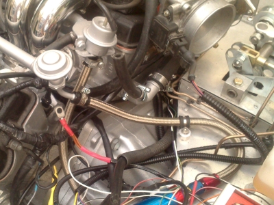
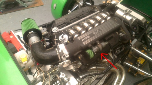
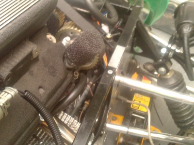
I needed to do something about the Idle Air Control Valve. The IACV is an ECU controlled valve which bypasses the throttle butterfly, and lets the ecu control the amount of air going in at idle. This normally takes its air from a small branch off the main intake, ahead of the throttle; however my intake doesn't have a port for this, and there isn't really room to run a hose from the IACV (which is bolted to the side of the plenum - arrowed below) round to the inlet pipe anyway. So I bought a smaller, secondary filter to go on the IACV, which looks a lot neater than running more hoses everywhere:
While this works quite happily, the sucking noise it makes at idle is phenomenally loud and obnoxious. I put up with it for a bit, but eventually plumbed it into the main intake hose which was actually dead easy. And much, much quieter.
With the filter in place, I could see about getting air to it. Having looked at various scoops, vents, naca ducts, and the like, I had to come to the conclusion that there really isn't enough space to do anything too clever. And the filter is practically touching the bonnet at its widest point, so I need to do some cutting away there whatever I do. So the simplest and smartest thing will be to cut some holes in the bonnet. Design to be finalised...
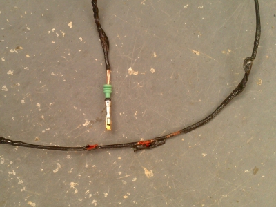
I was left with a few unused holes to fill. The crankcase vent used to go to an oil separator unit, a fairly large and ugly steel cannister which bolted to the plenum. This took a vacuum feed from the plenum, condensed any oil vapour, and drained it back into the top of the fuel pump housing. There's no space for any of that under the bonnet, so it gets replaced with a simple foam breather filter:
I blocked the vacuum port with a bolt and some silicone sealant.
I also managed a few nights working on the carpets, which I'd had a go at ages ago, but didn't really get past the practice stage. I did a couple of sections for real...and then the sewing machine broke. Repaired now but it seemed to fit the general "things going wrong" state of affairs. I'll do a full post about the carpets generally at a later date.
I did a few interior bits as well. Some checking for IVA-compliant radiuses in the cockpit, which lead to adding a few bits of trim here and there. Access panel (actually looks better with trim), and top of the handbrake cover (not so much):
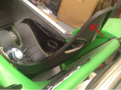
Seat backs: (heard of a few failures on this, so added some clip-on edge trim just in case)
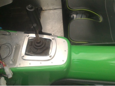
I was looking around for a gearstick gaiter surround, but due to the slightly offset position of my 'stick, and general modifications to the tunnel, none of the standard ones I could find would really fit. So I spent a couple of hours making one from 6mm ally plate, which I'm quite pleased with. I've ordered a bit of leather to make the gaiter from, at some point...