Reconditioning
Oil Pump
2nd July 2010
The first thing I tackled was the oil pump. The alfa manual gives very clear instructions on how to disassemble and check it.
It's an ingenious design, with one rotor offset inside another, very simple and sturdy looking. After cleaning, a visual inspection showed a small amount of scoring and a couple of little nicks, but nothing which looks big enough to matter, so I'll consider it ok.
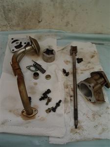
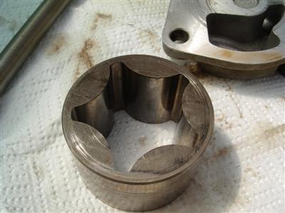
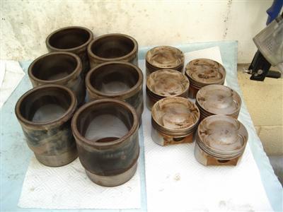
 Top left - all the bits cleaned and ready for checking. Top right - the outer rotor, some scoring on the top and outside visible. Bottom - inner rotor - the only damage visible were these tiny nicks on the edges
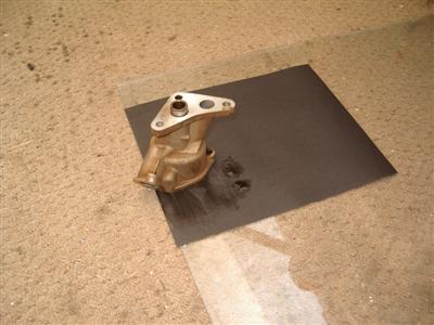
The clearances were all within the quoted tolerances, with the exception of the endfloat of the two rotors. This was about 0.001" larger than it should have been, probably because the soft aluminium case has worn. Fortunately, the EBH comes to the rescue here. It suggests simply sanding down the pump case to reduce the endfloat and bring it back into spec.
To do this, use 250 grit wet and dry paper on a sheet of glass, and gently run the pump case across it. Only a couple of thou' has to be removed, so it's a case of doing it a bit at a time, measuring frequently. I was a bit unsure when I first read it, but I have to say it was very easy and seemed to do the job very well. Not something I'd have thought of doing myself.
After that, it was cleaned again to remove any grit, and reassembled with a touch of engine oil on all of the surfaces. I was careful to locktite all of the external bolts.
Pistons
The V6 pistons are of the fully floating pin type, so can be completely disasembled and checked. Just by feel, everything so far has seemed to be very tight with zero "wiggle", so I'm not really expecting anything to be too worn - but I'm going to check anyway. I've had to buy a few new tools for this, a larger micrometer, a bore dial gauge, and a set of snap bore gauges.
The first thing I did was remove the piston rings - I did this by hand after trying one and it not seeming too bad - I might have to buy a set of ring pliers to put the new ones on though. Then I removed the gudgeon pins, which has to be my all-time favourite name for a thing.
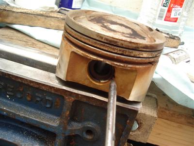
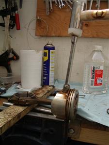
The pins are held in place by spring clips at each end. There is a little recess in the piston to enable you to get something behind them, I used a pointed tool and a pair of long-nosed pliers to pop one out from each piston. I left the other side in because there didn't seem to be much point in removing them both. That done, I very gently tapped the pins out, using a socket as a drift. Very little force is required, they're a sliding fit, just a tight one. Note that the rod end is supported on a bit of wood. It's all a bit wonky in the pic because I only had one hand to hold it all!

At this point, it suddenly occurred to me that the pistons have cut-outs for the valves...and I am fitting bigger valves...which means that the cutouts aren't going to be big enough! A quick phone call to my engine man confirms that they can machine a bigger cutout, so I need to get them packaged up and sent off. I'm still waiting to take delivery of my ring grove cleaning tool, so that will have to wait until afterwards.
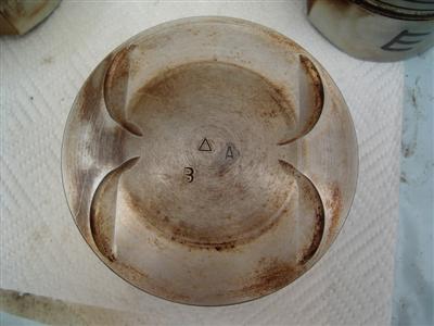 Cutouts need to be bigger! The Triangle and "B" are factory markings, the "A" is mine to identify which cylinder it came out of.
What I did do was to do the basic measurements and checks to make sure that they are worth re-using. Professional engine builders may want to look away now, or perhaps read on and laugh...
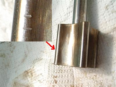
I checked the gudgeon pin bores for size using a snap gauge. Tolerance for this is tiny, 22.003 - 22.006mm (i.e. 3 microns). After practicing for some time, I think I might be able to get close to +/- 0.005, at best 0.0025, but I don't think I'd claim to be more accurate than that. Based on that, they all seem fine, commming out at 22.0025 - 22.005. Based on that, plus the unworn appearance of everything and the fact that it all feels tight, I'll consider them OK.
The pins themselves all seem spot on - I could detect no variation or taper on them, and again despite the tiny tolerances given, I think they're fine.
Harder was measuring the piston width. Pistons and cylinder liners come in 3 classes based on their size, termed A, B, and C. The factory marked them with the appropriate letter and a coloured blob to indicate which each was. Mine are all Bs.
This means that the width across the widest point of the skirts should be 92.935 - 92.945mm - a whole 10 micron window. Now I found it very hard to get repeatable measurements with the micrometer, because of the rounded sides of the piston. As you tighten up the micrometer, it tends to "walk" as it contacts the surface over the last quater turn or so and end up in slightly different spots, hence giving different readings. As a result, I doubt if I can get better than +/- 0.02mm accuracy. They all came out in the right ballpark, between 92.92 and 92.95. But, and it's an important but, visibly there is clearly no wear at all on the skirts (or anywhere else). All of the original machining marks are there, untouched (see pics). That being the case, I can't see how they can be any smaller than they came from the factory. So I'm going to consider them OK.
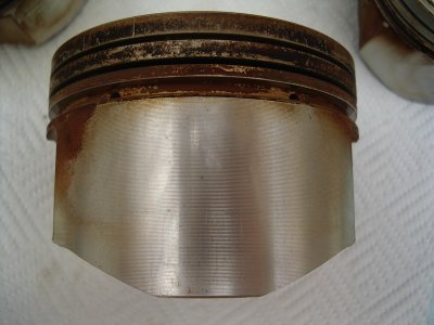
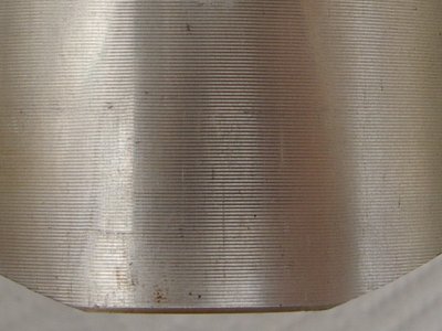
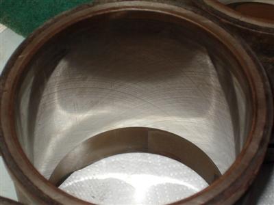
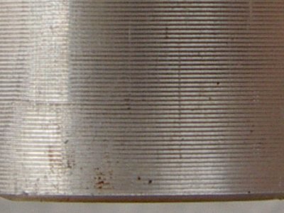 No wear visible on piston skirt - all pistons are the same
Big End and Main Bearings
I'll be fitting new bearing shells thoughout as a matter of course, but it's worth a look at the old ones. Big end bearings showed virtually no wear on the bottom halves, with wear in the centre of the top halves - as expected as this is where all the power is transmitted. Wear was consistent across all 6 sets.
On the mains, more wear was evident, with both halves much the same. Again it was the same on all 4 sets.
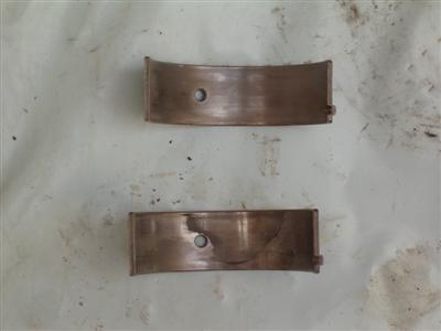
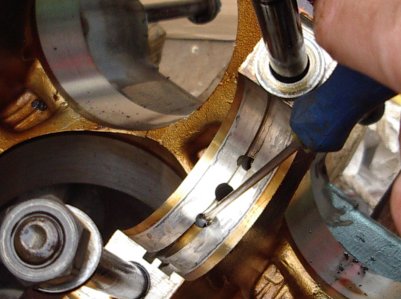
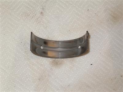 Left - big end (conrod) bearing shells. Confusingly, the top one is from the bottom half, the bottom one from the top half - it's more worn because it's transmitting the power downwards. Right - main bearing shell. All have the same wear pattern.
To my untrained eye this all looks fine for such a high-mileage engine, and the fact that wear is consistent is a good sign.
Cylinder liners
To the eye, these appear to be in good nick. The crosshatch is visible all the way down, no ridge can be detected using the "fingernail test" (dragging your fingernail up the bore to look for a ridge at the top of the piston stroke), and there are only a few patches of obvious wear.
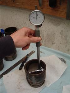
They are nominally 92.995-93.004mm internal diameter, and need checking for size, taper (top to bottom), and out of roundness. Both out of roundness and taper should be less than 0.01mm according to the manual. For this I used my newly-aquired dial bore gauge. This is considerably more accurate than the snap guages; for one thing, it self-centres, and for another, the dial makes it very easy to tell where the largest measurement across the bore is. It's also very reproducable, so I am pretty confident that I can get accuracies of 0.0025mm. Again, a fair bit of pracice and callibration was required first! Then I recorded the max and min diameter at the top and bottom of the bore.
As expected, maximum diameter is perpendicular to the crankshaft, because the side loading on the pistons gives more wear there.
The outcome is that all cylinders are good for taper - one has a perfect zero, one has 0.005mm, and the rest have 0.0025 - pretty good. Out of round was not so good - the two at the flywheel end were both 0.0125mm wider in one direction than the other. And for size, all but one are out of the nominal size - all between 93.005 and 93.015. Again, the two at the flywheel end were worse.
I find this a bit odd, since there is so little visible wear - surely the crosshatch would have been worn away by 0.01mm of wear? However, repeated recallibration and more measurements have convinced me that the results I'm seeing are correct. So I may have to be shelling out for some new liners.
8th July 2010
Well, some good news. I asked on Pistonheads for some opinions from the resident engine builders, in this thread. It confirmed what I was saying above - there has been no wear and the tolerances are well within normal practice, which would be to a thou (0.01" or 0.025mm). "Slap it back together quick and leave well alone" being the advice! Equally, the EBH worries mainly about taper, which is fine, so I won't be worrying about new liners.
I have checked the ring gaps however and they are well over, around 0.6mm rather than 0.4, so I will fit new piston rings and get the bores lightly re-honed so that they run in properly.
Core Plugs etc
There are a few more bits to be dismantled from the block before it's cleaned. Firstly, the oil filter mount, which also forms one of the engine mounts, is a separate moulding. It's quite a complex piece, it has a thermostat to route oil through the oil cooler, a pressure valve (which I presume bypasses the filter if it gets blocked), and a sensor (oil temperature I would guess).
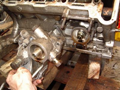
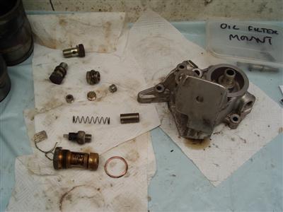
Easy enough to take apart though, nothing particular to report. All very clean (well, oily, but clean oily if that makes sense) inside, no deposits or clogging up.
Then I moved on to the block. The book says to remove core plugs so that the oilways and waterways can be cleaned out. Kindly, alfa have made most of them screw in plugs, rather than the push in type. Most of them came out ok, although they are tight and sealed in, so an extension bar was sometimes required.
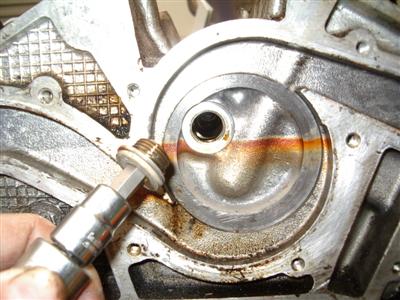 Main oil gallery plug, confusingly inside the waterpump
It's pretty simple actually - there is a plug at the end of the main oil gallery which runs front to back, and that's really about it. Straight passages then run from here to the main bearings. There's one straked plug behind the oil pump which I've not bothered removing as it's only at the end of a short, 2-inch passage.
There are a few more plugs into the water jacket, however this is again very simple because the water flows around the cylinder liners, and with these gone, there are very few small passageways - everything should be easily reachable with a long test-tube brush.
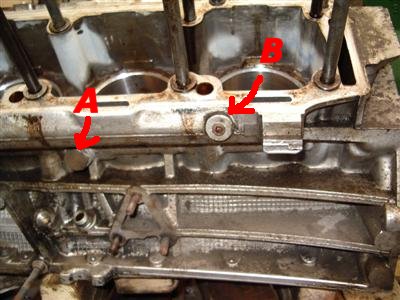
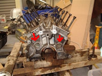
There were a few I didn't remove. The one marked "A" below is on both sides, I removed one but it just goes into the space between the cylinder liners - you can get at it from the inside easily, so not much point taking it out. The one marked B is again on both sides, but the bolts were looking quite siezed - I think I would knacker them trying to get them out. Again, it looks as if there is plenty of access from the other side, so I just left them alone. Finally, the two very large press-in plugs at the rear of the block look like having "world of pain" written all over them - I think I'd cause more problems trying to get new ones in and sealed than I will ever solve by taking them out. After all, it aint broke...
I also removed the spindle for the tensioner I couldn't get off on the previous page. I'd been confused because it didn't look like the ones in any of the manuals - this is because it's not the timing belt tensioner. I found that in a bucket of parts I'd removed months ago. I think that this is just a sprung jockey wheel. Anyway, the spindle is very badly pitted, so it has to be replaced. Now that the block is clean of other protruding bits, it was, although tight, easy enough to get out with a very large adjustable spanner.
Final thing to check before moving onto bearing housings and the likes is the piston oil jets. These are holes in the main bearing castings which squirt oil upwards onto the bottom of the pistons, cooling them. They have little spring loaded ball valves in them, which the manual says should be tested using an air line. I don't have one of those, so I simply poured some white spirit into the bearing housing and pressed the valve gently in with a screwdriver. All of them were fine, the spirit drained through straight away so no blockages there.
Then I scraped off the gasket surfaces (with a gasket scraper, oddly enough), to remove old sealant and bits of stuck gasket. The block now needs a good clean - I've bought some long test-tube brushes to do the various galleries, for general cleaning I'm toying with the idea of the local car wash + a can of muc-off. It's such an open casting it looks like it will be pretty easy to do by hand.
Block Cleaning
17th July 2010
And that's exactly what I did. Friday lunchtime, block and sump in the back of the car (the block is easy enough to lift around now that it's empty), and down to the jetwash. I bought a couple of washing up brushes and a can of muc-off, and with half an hour of scrubbing and jetting, had the block properly clean. The high pressure hose made a good job of flushing all the much out of the water and oil galleries, and spraying it all over me, the walls, passers-by etc. But the block was clean! I guess you'd have to be careful doing this with an iron block because of rust, but no such worries here, just take it home and let it dry out.
So the block, at least, is now ready to be rebuilt. But I've been thinking ahead, and know that I want to paint the plenum and rocker covers. It'll look odd, I think, if the block and heads aren't also painted - although clean, there is a bit of corrosion (aluminium seems to grow a crusty bloom on the surface). So I bought a couple of cans of "aluminium" engine enamel and painted the outside of the block. Painting took maybe 10 minutes, masking it all up took ages! But a lot, lot easier to do it now. That took a few evenings what with waiting for each coat to dry etc.
I cleaned and re-assembled the oil filter mount. I got hold of some automotive silicone sealant first, since all of the plugs had sealant on the threads. No problems there, apart from putting it all together and then noticing that the spring for the pressure valve was sitting on the bench. Cue some rapid disassembly and reassembly before anyone noticed...
Previously, I'd checked the oil thermostat, by boiling it in a saucepan of water and making sure that it opened, which it did.
Con Rods
Then I finally got around to measuring the big ends of the con-rods. They seem quite oval to me (at worse by over a thou) - I know that they can stretch and ovalise that way, but at least two of them seem wider horizonatally than vertically, which seems very odd. Anyway, I've found a local engine shop that is going to re-hone the cylinders for me, so I took the con-rods along to get a professional opinion. "We'll have a look and rehone them if they need it" he said, so in their (hopefully) capable hands it is.
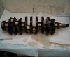
Crankshaft
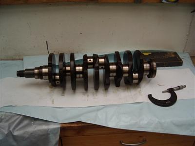
I also measured the crankshaft journals, mains and big ends, and all are spot on - no detectable taper or oval on any of them. As an aside, all of this measuring has meant that I purchase a whole load of micrometers and gauges. I bought a couple new, then had a peak on ebay and found that there were thousands of used ones going. A few speculative bids saw me pick up a set of Moore and Wright micrometers for under a tenner, all still in perfect order - definately the way to go.
I haven't cleaned the crank yet, I've kept it well oiled as I can't risk any rust on the journals. I intend to clean it just before I fit it properly. The manual says to remove a set of plugs to clean the internal oilways (oil is pumped through the crank, from the main journals to the rod big ends), but again it looks like an opportunity to do more harm than good. A flush through with solvent will be fine I'm sure.
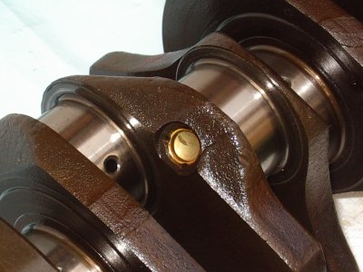 Right hand pic shows one of the straked oil plugs that you're "supposed" to remove to clean out the oilways. Bugger that.
So it's all about ready to start going back together again. For this, I need to get hold of a new set of gaskets and seals, new bearings, new rings etc. I contacted an Alfa dealer for a gasket set, which apparently is Ł330(!). So I'm trying my local motor factors first, though they're having trouble finding supplies. Still, I can wait a bit since it might save two hundred quid or so. Bearings and rings I might have to source myself since the factors doesn't do them, and gawd knows how much the dealer will want. So a bit of work to be done there.