Engine Stripdown
25th June 2010
So the time came to start stripping the block in ernest. If you've found this page first, I did the heads earlier, on this page.
My companions during this are the rebuild manuals for both 24v and 12v engines (download links on the Information Page), the "Engine Builder's Handbook" (EBH), and a couple of very useful threads on the alfaowner forum:
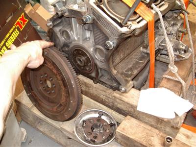
Anyways, first step is to remove the crank pully / damper. This is reknowned for being "a bit tight".
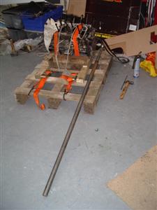
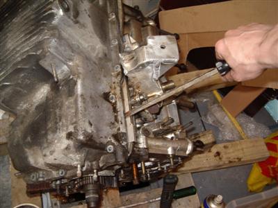
The crank needs to be braced to prevent it from turning. Alfa have a tool which screws on and locks the flywheel, other people have used screwdrivers, crowbars etc. I knocked up a tool from a bit of 10mm bar and 3mm plate, which bolts onto two of the gearbox bellhousing holes:
So then, it's "just" a case of undoing the pulley bolt. This is a 41mm bolt, which is conveniently the same size as the rear hub nuts on the sierra, so my Draper "hub nuts" socket fits. It also has a locking tab which needs bending out using a screwdriver first.
The first few attempts using a 3-foot 3/4 inch drive breaker bar and a helper to hold the engine down didn't even touch it. Helping it with WD-40, a bit of hammering and heating with a blowtorch also had no effect. Clearly it was very tight.
Step two was to lift it onto a pallet (easy enough for two people now that the heads are off it), strap it down, and take a 6-foot extension bar to it (kindly loaned by a neighbour). With the missus stood on the pallet for some extra ballast (not adding very much I should say!), and me litterally hanging my full weight on the end of the bar, it gave in without any more of a fight. So we're looking at over 700 ft-lb of torque! "A bit tight" indeed...
It was then easy enough to remove the pully itself just by "wiggling" it off by hand.
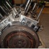
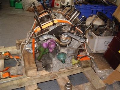 Green - timing belt tensioner. Purple - tensioner pully. Light Blue - timing belt pulley. Yellow - crank position sensor
Next up was the crank position sensor. An easy two bolts you say...but no! One was well and truely rusted in, and the socket head was rounded off - someone had been here before. And it would be the innacessible one of the two. After about 40 minutes during which the old "hammer a larger allen key in", "cut a slot in it and use a screwdriver", and "hit it with a big 'ammer" tricks had all failed, I gave up and drilled it out, which took about 3 minutes.
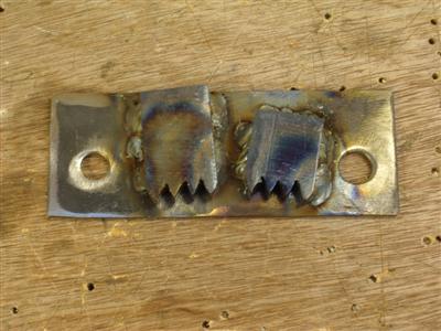
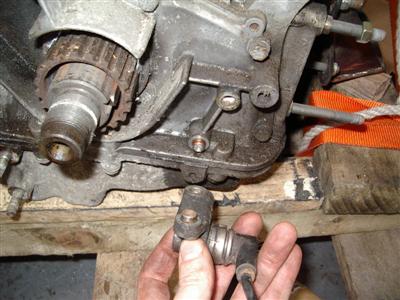 The screw holes have two non-threaded steel inserts
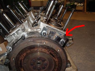
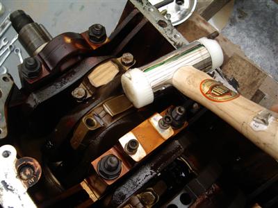
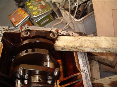
Now the tensioner. Unfortunately, the one I have is different to both manuals and anything I've seen on the 'net:
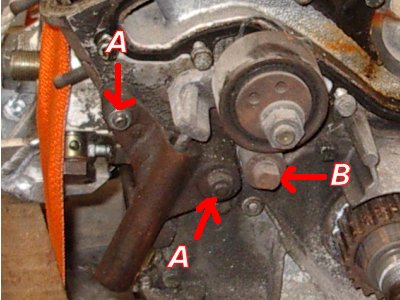 The tensioner piston is held on with two bolts (A). This pushes on the tensioner pulley, which rotates around a stud (B)
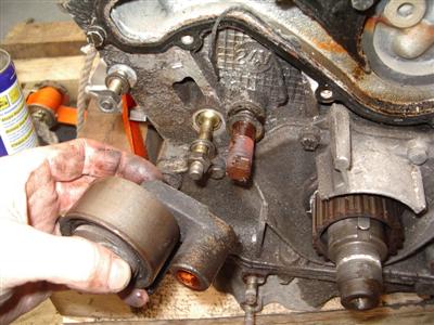
The tensioner came off easily, but the pulley doesn't want to come off the stud. There was a circlip on the end which came off without too much trouble, but it still wont budge, despite rotating around it. The stud has flats on the end, but I've been unable to unscrew that either. I'll see if I can find any info before resorting to brute force & ignorance...
25th June 2010
Well, having given it a good dowsing in WD-40 and leaving it to soak overnight, I levered the tensioner pully off without too much trouble.
I then nipped around the back to remove the flywheel - nothing major to report here. Whilst I was there, I weighed it - 8.0Kg in case anyone's interested.
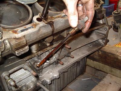
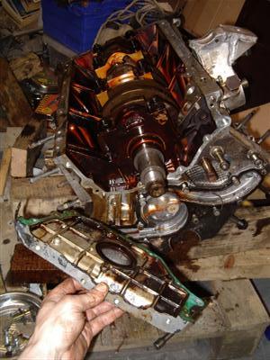
Almost time to turn it over - first, remove the two pinging sensors which are in the valley between the two heads, and secondly the dipstick tube, and next to it, a sensor in the sump, which I presume is for oil temperature:
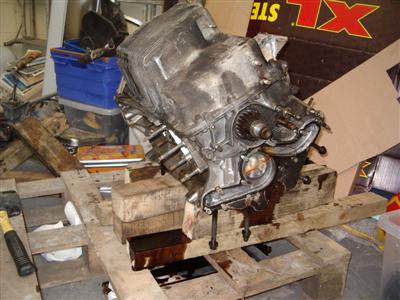
Then, I piled up some bits of timber to make props, and turned the engine over so that it was sitting on one of the head faces. The timber is to hold it up so that the head studs don't have any weight on them. Two bits of 3x3 under each cylinder works well.
Turned it over easily enough, but it did all go a bit "BP", there was still quite a bit of oil left inside! My oil tray wouldn't fit under the pallet, so I improvised with the lid of one of my storage tubs.
 Granville, f-f-fetch a cloth
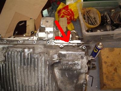
Unbolted the sump, easy enough. Didn't want to budge though, even with no bolts and a bit of persuading with the rubber hammer. There isn't really any overhanging bits you can get any purchase on. Then I spotted a hole which is half covered by the sump flange, almost as if it was put there specifically to get a lever in. Was it? Who knows, it works perfectly though:
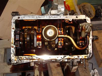
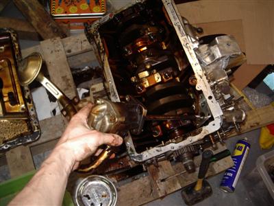
So sump off, and the first view of the bottom end. A bit of debris in the sump, but it all looks to be bits of sealant.
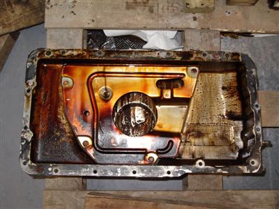
The sump seems reasonably well baffled, though I'm still not sure if it will be too tall - I may need to chop a bit off of the bottom and widen it. But there seems to be plenty of space below the crank to do that.
So I return to the bottom end. And what's this?
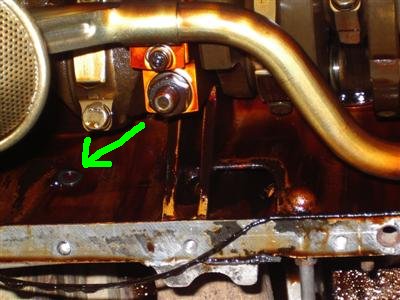
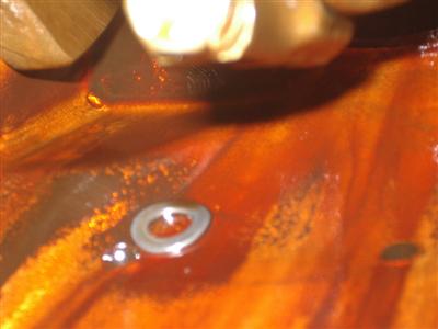
At some point, someone has left a washer floating around in the crankcase. Gawd knows how long that's been in there - it's a bit battered but I can't see any damage to the crank, so far at least.
Next thing, according to the manual, is the oil pump. I'm on the 12v manual here because my '93 model engine has the older style of oil pump - the later ones had a chain driven affair. The manual helpfully says "remove oil pump". But how do you get at this bolt, hidden away underneath the pump?

None of my tools would reach, so I resorted to grinding an allen key down until it was short enough to get in, then undoing the bolt a painful quater of a turn at a time. I guess they must have had a special tool in the factory, though the manual doesn't mention one. That done, the other two bolts were easy, and the pump goes into the box of bits for checking and reconditioning.
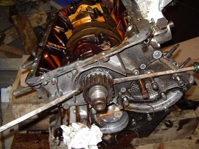
Finally for tonight, I removed the timing pully and front cover. The pulley came off easily enough by levering on both sides with screwdrivers, and the cover is a simple bolt on job:
2nd July 2010
This isn't quite a true order of things, as I tended to clean and dismantle each bit as soon as I took it off, because they're obviously swimming with oil. But I think it's easier to follow if I show the dismantling of the block, then the cleaning/dismantling/checking of the component parts afterwards.
So now it was the turn of the pistons and rods. First thing I did was to stamp the two halves of the rod with a letter so I knew which bore it came from. It should be the cylinder number really, but I don't have any number stamps. As it turns out, they are already marked by the factory, though the markings were a bit baffling to me to begin with. Anyway, they're marked twice now.
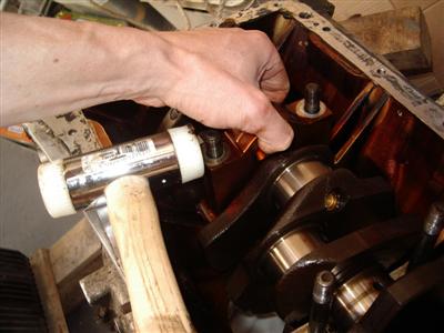
Undo the rod bolts. The caps are very tight, as there are roll pins holding them together in addition to the bolts, so a gentle tapping on either side with a soft mallet is needed to pop them off. Lift off the cap, and the half bearing shell comes out with it. Then remove the cylinder linder retainers, and using a length of 1x1/2 inch timber, gently tap the rod, piston and cylinder liner out of the head-end (currently the bottom because it's upside down!) of the block.
 Left: Tapping off the big end cap. Right: Cap off - piston and rod is then removed by tapping it downwards and out of the bore.
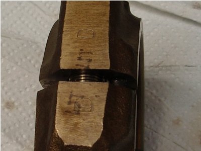 Identifying marks ("D") stamped on both parts of the rod. Note also the factory-printed number 5, D'oh!
One thing which was quickly obvious was that I should have left the flywheel on, so that I had something to turn the crank with to get at each rod. I re-inserted a couple of flywheel bolts and used a long screwdriver between them to turn it over.
Only about half of the cylinders came out, for the rest the rods and pistons came out, leaving the cylinders in place. I will remove them when I've taken the crankshaft out and have more room to work.
So that just leaves the crankshaft. This spins very easily by hand now that there are no pistons attached, and has no discernable play, which I take to be a good thing.
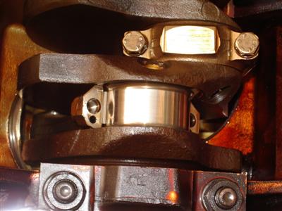
The main bearing caps are removed one at a time from the front. A long extension bar and 19mm socket are needed for this, they're about as tight has head bolts. Once the nuts are removed, the bearing cap itself is still very tightly fitted in their registers, and can't be removed by hand. Alfa do a special levering tool, but as per the Engine Builder's handbook, I gently tapped each side with a soft mallet and wiggled and pulled:
As with the pistons and rods, I stamped each of the caps to identify its position and orientation
The rear main is much bigger than the rest, and has no "mallet access" from the sides of it. I used a length of softwood to lever it up, a little on each side at a time. It has an indent on each side for the official tool to go into, I just used this.
Once all those were off, the crank can be lifted out. Interestingly (I thought), it doesn't spin freely when just sitting on one half of the bearings, only when the caps are on. It is, naturally, rather heavy. I stored it on the flywheel flange as recommended in the EBH to prevent warping, tied to the bench leg to stop any accidents, in a tray to drain:

So that's about it for the stripdown - on with the cleaning and checking...