Fuel Tank, Rear Tub, and Wires...
24 August 2010
Made a start on the fuel system over the last couple of days, a lot of which has been research and working out which way to do it. The first practical part is fixing the fuel tank.
Now the standard tank sits in its frame and is held down by two metal straps, which are bolted into the frame. My modified tank is different, and has a mounting flange which can be bolted directly to the frame.
The manual suggests using self tapping bolts here, but as a wise man once said, they are the work of the devil. So I'm drilling right through the frame rails and bolting it together with M8 bolts and nylock nuts. This means that some of the bolts will also work to hold on the rear tub, two jobs for the price of one! This dose have the downside of meaning that I won't be able to finally torque up all the tank bolts until I finally fix the tub - which won't be yet. It'll be comming off a few more times I'm sure for wiring etc.
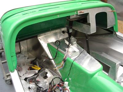
First job was to locate the tank, mark out and drill holes in the mounting flange, then matching holes in the rails. I painted up the edges of the holes to help keep the dreaded rust at bay. With that dry, I was able to offer up the tub so that I could mark and drill the four holes in that. First, I had to make new a cut-out in the tub for the large central collector underneath the tank.
The points where the tank itself touches the chassis frame are lined with sticky-backed foam (comes with the kit), then I could bolt it all together. The tank mounting flange is actually a few mm too high, I think because the design didn't take account of the fact that the tank sits on two metal straps rather than just hanging through the frame. No great bother, but I've put four washers between the frame and flange to make sure that nothing is stressed out of shape. Before putting the tank in, I rinsed it out with fuel as the fabricator instructed, it seemed totally clean though.
The front bolts hold the tank firmly even when just nipped up, so I can safely fix all of the plumbing and finally torque it all up when the rear tub goes on for good. I will probably put a few more bolts through the tub into the rear of the frame as well, I'll use rivnuts here.
Whilst I was doing all of this, I also painted the inside of the tub and tunnel mouldings with green gloss, as I've been doing with all of the GRP.
Plumbing and the Tunnel
So now it's time to think fuel plumbing. This bit scares me a little, having seen a few horror stories on the web of kit cars which have burned to the ground because of fuel leaks. Some because of propshaft failures (see below), the other dangers are fuel lines fretting and wearing through, or unions poppping off in the engine bay and spraying fuel around. This is all running at 43psi as well, so you do not want a leak. Dangerous stuff, petrol.
It's not just petrol either. The whole transmission tunnel area looks like a <Watchdog>Poteeeeential Deathtrap</Watchdog> You've got brake lines, electric cables, and fuel lines, all passing an inch or so away from a big wirling shaft doing 7,000 rpm. Nice. In the interest of learning from others misfortunes, I spent an evening collecting examples of propshaft failures and the unpleasant results:
- Tim Hoverd's Fury - loose propshaft bolts caused the shaft to come off and rupture the fuel lines in the tunnel, car burns. Later rebuilt.
- Prop off at 50mph - Prop fails at engine end, collects wiring loom, pulls all wires out of dashboard and engine bay, taking out brake cylinders, coolant pipes, gear linkage...
- Prop Snapped at HIGH Speed - Prop sheared, and "...tried to beat its way out of the tunnel. did alot of damage, cut thro brake pipe, fuel pipe, wiring etc. bent the chassis big time in the tunnel, lucky it wanted to come out thro the passenger side."
- Propshaft Failure - Snapped prop, only minor damage here as it seems to have had a prop catcher in place.
- My car is no more - Snapped prop, ruptures fuel line, car burns and is utterly destroyed. Photos have gone now, but I was totally shocked when I saw this one. There was almost nothing left.
Ouch. Don't fancy that much. So I'm going to ensure that (a) I have a prop catcher in case it breaks; (b) make sure that all wiring, lines and hoses are the other side of a chassis rail to the propshaft; and (c) use quality steel braided fuel line throughout.
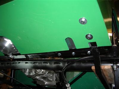
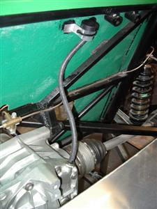
I can't make the prop catcher yet, because I don't have a prop; however I do need to get the brackets for it welded onto the chassis before I put any more lines in there. I made these from a couple of lengths of box section I had left over from making the handbrake bracket; each has two m8 holes in for bolting the catcher to.
A catcher is basically a steel hoop which is designed to stop the prop flailing around if one end breaks. Ideally you have one at each end, however mine will be very short, and the chassis is a bit short of space at the front. Providing I make the hoop small enough around the shaft, it should do the job. It'll certainly protect the brake and fuel lines (not to mention occupants) from damage.
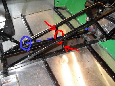 Red arrows show the new uprights, the red circle is where the hoop will go. Blue circle is where the gearbox output flange is, with the blue line showing the path of the shaft.
So my plan at the moment is to use single runs of steel-braided hose (copper pipe is often used, but you still have to use flexible hose to get around the tight bends = more joints). I don't think I can run to Aeroquip or Goodridge at �20 per metre and �35 per connection(!), but there are a few cheaper options.
Wiring the Tunnel
15 September 2010
Been away on holiday for a bit, which was nice. Now back to torrential rain and gale force winds, how rare.
Before I left, I priced up some fuel line options. Because I have JIC fittings on my tank, I'm really steered down the route of using "proper" (i.e. expensive) aeroquip style fittings and hoses anyway. Speedflow seem to do some nice ones which are a bit less pricey than the other two, but it's still looking like around 300 quid for the lines, pumps and filters. Anyway, since I'm still thinking about that, I made a start on some wiring since I need to do that as well, and I had it sat in the loft.
I've got the standard Dax loom, which comes in 3 pieces; engine bay (front), interior, and rear. The front and rear looms are easily identified because they are wrapped in black loom tape, whilst the interior one is a big bundle of unwrapped wires with a fusebox and bunch of relays. It doesn't look too big when you get it all out of the box:
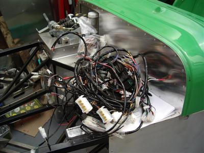
I spent probably an hour working it out, (instructions are provided which list every wire by colour), and roughly layed out the front and rear sections on the car. To begin with, I roughly cable-tied them in place, just to see where everything was. The only job I really need to do right now is to get the wiring fixed down the tunnel and into the rear tub area, the rest can be done as I go along.
Both front and rear looms enter the scuttle area, where they join with the interior loom. So an early job was to drill the holes, add the grommets and feed the wires through. This also required a slot cutting in the front of the tunnel so that it can still lift on and off:
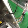
At the rear, it was clear that the fuel pump cable came out of the loom in the wrong place - Alex also found this. So I ordered some loom tape, unwrapped that section of the loom, then re-wrapped so that the fuel tank wire came out further forward.
To fix the cable, I've gone with convoluted split trunking, held on by cable ties and nylon p-clips where necessary. This is nice and fast, plus gives the cables some protection. Cheap as well. I've put a few turns of loom tape around the chassis where the cable ties sit, just to prevent any chaffing. My cable runs out of the rear tub, up along a chassis member, crossing over to the outside of the driver's side chassis rail, (out of the reach of any flailing props!), up the handbrake bracket, and up into the underside of the tunnel:
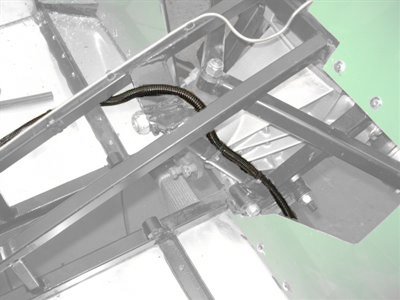
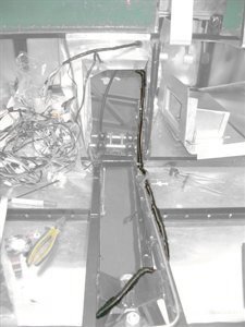
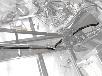
It means that the fuel and electrics have to cross over to opposite sides at the rear, but there isn't room for both fuel lines on the driver's side, and the rear loom has to go on the passenger side of the tub, so it's the only way to keep the two separate for most of their length.
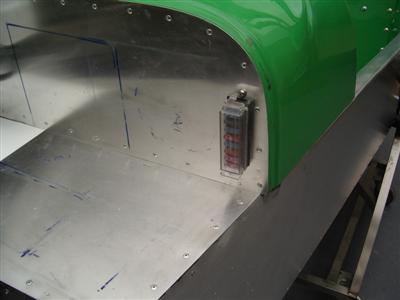
Whilst I was in a wiring mood, I also fitted the fuesbox. This usually goes on the front of the scuttle; I spent a bit of time deciding where the battery, header tank and ECU would have to fit, (which also meant looking at which ones I would eventually buy so I could get the measurements), and decided that the fuses would go nicely on the far passenger side of the scuttle:
Odd 'n' Sods
There's also been a lot of odd jobs going on - spraying the engine block with sliver engine enamel was one. I've also fitted the brake fluid tank and low-pressure lines to the master cylinders:
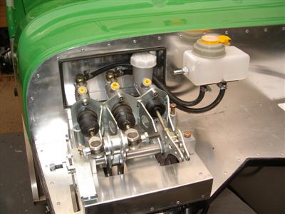
Ideally, this should all be above the cylinders - but there isn't room, so you have to just fit it as high as possible so that the outlets from the tank are higher than the inlets to the cylinders. I've routed the rubber hoses behind the clutch cylinder which I think looks neatest - I've put some sticky foam strip on the back of the cylinder to prevent chaffing. Now I just need to block off the unused outlet for the clutch cylinder.
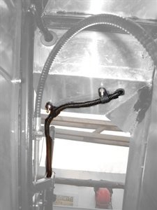
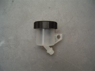
The other job which has been waiting around for ever was to put a catch tank in for the differential breather. The diff can apparently throw out a bit of oil on track days etc, so it's common to fit some sort of catch tank. I've used a cheap motorbike clutch master cylinder from eBay which should do the job nicely. A simple aluminium bracket bonded to the rear bulkhead with wurth, and it holds on with a cable tie. Needs a longer bit of hose so that it can route under the boot tub, which I will source at some point:
Finally, I had a call from Cat Cams who are making up my cams and vernier pullies. They only had one pully which I'd sent down to use as a pattern - but they'd noticed that the driver's and passenger side pullies were different (I hadn't). So I sent the rest down to them to copy.