He's got the horn.
More Odds and Sods
30 September 2010
Garage time has been a bit sparse over the last few weeks, so I've confined myself to finishing more of the little (and not so little) odd bits that are mounting up.
Rear Tub
Finishing the rear tub mounting was one - I've used a series of M6 stainless bolts at the rear edge, bolted into rivnuts in the fuel tank frame. As usual I painted all of the holes before putting the rivnuts in, and I will use locktight on the bolts on final assembly. I haven't done anything with the front edge yet, as I'm going to be fitting an undertray to close up the big hole under the tub ("the parachute"), and this will (somehow) attach to the front edge of the tub moulding.
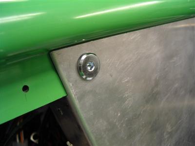
In the cockpit, I've used 4 bolts on each of the curving shoulders to attach the tub to the corner panels. The manual says to use rivets here, and self tapping bolts with a layer of wurth elsewhere - but then you'll never be able to get it off, which has caused some people problems. So I'm going with the "removable" option - I can't see that it has any particular downsides.
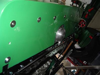
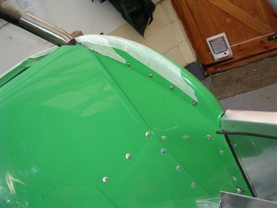
One slight problem was that I trimmed the tops of the corner panels down a bit too far - so the 4 bolts (RH image above) are rather close to the bottom of the moulding edge. It's not a problem, but just doesn't look quite as neat as I'd have liked.
Scuttle Wiring...
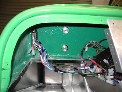
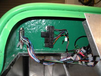
It seems to me that the wiring is easiest to make sense of when you can start attaching bits of it to actual components or bits of the car. I don't have many components yet, but the relay box is already fitted into the loom, so I figured I'd mount it somewhere so at least that's another fixed point.
The easiest way seemed to be side on to the scuttle wall - but I didn't want bolts going through the front. So I turned down a couple of short lengths of ally bar to make spacers, about 10mm thick. I drilled and tapped an M6 hole in the middle, then wurth'd them to the inside of the scuttle, and the relay box can then be bolted into the holes:
Scuttle Trim
Another small job I've been meaning to do for ages was running wing piping along the bottom of the front (engine-bay side) of the scuttle. Not that exciting, but finishes it off nicely, and is necessary so that it matches the outside edge which will also sit on wing piping.
Dashboard Bolts
I wasn't entirely happy with the round head allen bolts I was using to hold the dash in - they were a bit proud. So I looked around, and found some bolts which have a wide and much flatter head, which I think will look better, especially on the covered sections. These are "furniture bolts", but hey:
Tachometer Pod
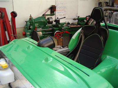
I'd been waiting for ages for my gauge pods to arrive, seems they were out of stock everywhere. In fact, I could only find one brand of 80mm pod, which is by LMA. I promptly set to chopping bits out of it so that it would blend into the top of the dash. This was a real trial-and-error job, even using cardboard templates to start with, as there are absolutely no straight edges anywhere, it's all compound curves. Anyway, after much careful filing, I had a pod which fitted where I wanted it. In order to attach it, I made up a small bracket out of 1.5mm stainless, welded a nut to it, and glued it into the pod using araldite epoxy. I didn't want to risk welding it, because the pod is quite thin and I didn't want to burn a hole after all that work!. One hole drilled in the top of the scuttle, and a bolt passes up through to hold the pod in place:
Importantly, the screw will be accesible from inside the scuttle even with the dashboard on (have to remove the steering wheel and shroud), because it sits on top of the dashboard. I had to move it a bit further into the cockpit than I originally planned, so that it didn't touch the windscreen, but only by a couple of centimetres. But I'm rather pleased with the look, and it "feels" right when sitting in the driver's seat:

My original plan was to do the same for the speedo, but place it behind the steering wheel, and a bit lower down. It looked like it would just fit, but now I actually have the pod in front of me, it's going to be too cramped, and would always be partially obscured by the wheel. So I need to rethink there. I could put another pod next to the tacho one, which would look quite good, but a) it's getting a bit too far over to see easily, and (b) I think it would detract from the visibility of the tacho. With just one thing there I think it will be nicely visible out of the corner of your eye, with two things I think the extra clutter would mean you have to actually have to move your eyes and focus on it. So I'm thinking maybe a small, square digital speedo to go behind the steering wheel, or perhaps a smaller dial one.
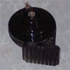
Horns
I'd rescued the horns from the donor alfa because they sounded good, and I liked the idea of reusing bits where possible. They were in a pretty bad state though, one in particular was very rusty, and the mounting bolt had sheared when I unbolted it. I'd previously gone over them with the wire brush when I was reconditioning everything, and they still seemed sound enough underneath.
So first job was to weld on a new mounting bolt. I just used an ordinary 8.8 M5 bolt. I was a bit worried that the heat might kill the internals, so I took it very slowly, welding a very small bit at a time, and used a wet sponge to cool it down between each weld. This lead to a rather more "blobby" weld than I'd have prefered, but when I connected it up to a spare car battery, it still worked! So I was happy with that.
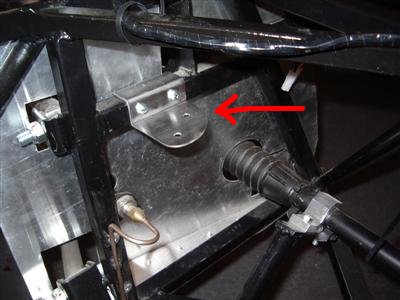
In order to kill the rust, I gave each a couple of coats of PQR-15, then rustoleum black on top. For mounting, I made up a bracket out of 1.5mm stainless. This sits over one of the chassis members and is bolted through with M5 bolts. I thought about rivnuts, but bolting through actually leaves much smaller holes in the chassis.
I will have to change the earth connectors on the loom, but I think I can manage that.
Earthing Points
Speaking of earth connectors, I was considering how to do the earthing points on the chassis. Apparently, bad earths are the source of some very weird electrical gremlins, so a bit of effort now might save hours of head-scratching later. Common methods are to use a self tapping bolt, or a bolt and rivnut, into a chassis member. However, I'm a bit paranoid about leaving large, unprotected holes in the chassis. We get a lot of rain, and things rust around here for fun. So I've decided to copy what another builder has done, and make up some small steel threaded studs which I'll weld to the chassis. The threaded hole won't go all the way through, so there's no way into the inside of the chassis member. The contact will be perfect because it's welded. And it can all be painted except for the very top surface of the stud, keeping the rust away from the structural bits.
Plus it gives me an excuse to try out the new lathe tooling I just bought
Fuel System
After much pontificating and research, I finally bought the bits for the fuel system. I reckon that the saving I could make by doing it the cheapest way (copper pipe and rubber hose) over using braided hose and JIC fittings is between 100 and 120 quid. A fair whack, but in the end I decided that I'd rather pay the money and have something which should last much longer and which should be more secure and hence safer.
I looked at Goodridge, Speedflow, XRP and Aeroquip. All are priced a bit differently, some have more expensive hose and cheaper fittings for example. In the end, and to my surprise, Aeroquip came out cheapest by about 20 quid, with Speedflow next. So I've ordered all of those bits, plus the filters (2, one before the pump and one after), and pump. I wasn't really prepared for how much the components cost, the filters particularly, which themselves are over 100 quid! Anyway, it's all ordered now, so I should be able to get that fitted soon.