Engine, Steering Wheel, Bodywork...
17 January 2010
Well, the snow finally melted, after a month, and temperatures are back (just) above freezing, for the first time in a month. Still cold in the garage but no ice on the inside, which is an improvement.
The build's in a bit of a funny place at the moment - lots of "need to do x,y,and z before I can do d, e or f" moments, so I've ended up doing several odd, unrelated things at once.
Engine Tuning
This is the biggy. After much head scratching, soul searching and pondering, I've come to the conclusion that the supercharger aint gonna fit - at least not without serious compromises which I'm not willing to take. So I'm going to go down the normal NA tuning route. I'm quite happy with this, the supercharging idea was always a cost-saving measure rather than because I particularly wanted it, and I do like the purity of naturally-aspirated engines. Less complexity, clutter and weight - but probably slightly less power (or more cost!)
That decision made, I've been putting out feelers for advice on exactly what to do. There aren't many people who have actually tuned this engine; lots of people talking about it, but not many who've actually done it. So far, the best information I've had has come from the alfaowner and stratos owner's club forums. AHM are the main company doing tuning, and have a great reputation, but aren't cheap.
The first thing many people do is to fit independant throttle bodies. Now I'm not an expert, but as I understand these things, the main benefits of these are basically (a) less restriction, and (b) some benefits to mid-range because you stop the air pulses from one cylinder affecting its neighbours.
That's all well and good, but (a) only applies if the current inlet tract is limiting airflow. (b) is all good, but ITBS bring either great expense, and/or great complexity (with homebrewed setups, getting them all syncronised etc); they can take up a lot of room, and unless you run them into a large air filter box, can actually reduce airflow if you use individual air filters on each one...(or so I've read)
So although it may be swimming against the tide somewhat, I'm not that enamoured with the idea, unless I know for sure that the limiting factor is the standard inlet setup, in normal use. It may well be on a race engine, but if it only matters at 6000rpm and above, it would seem a poor way to invest my limited cash. Plus they are a bolt on part; I'd rather get the innards of the engine sorted whilst it's apart, I can always change inlet tracts later on.
Then we have camshafts; a fairly standard method of tuning. The standard ones are by all accounts quite mild; there are a few aftermarket "fast road" ones available, so I guess ultimately I'll just pick one. The main problem would seem to be setting them up; I can't find a supplier of vernier cam pulleys for this engine, which would make fine adjustments a bit of a pain.
A custom exhaust is a given, again a tuning staple, and apparently there are significant gains to be made here, which is good news
The standard ECU is an old type with a non-programmable chip. I didn't know much about ECU types until I started reading around, but it means that upgrades are limited to replacing it with a new chip; obviously this prevents any sort of custom set-up on a rolling road. So it's going to be essential to replace this with an aftermarket one to get the benefits of any modifications. Downside is that they cost - 800 to 1600 pounds or more. Upside is that it means I can replace the horrible "flapper" air meter which weighs about a kilo and must restrict the airflow, with a modern Manifold Air Pressure sensor which does neither.
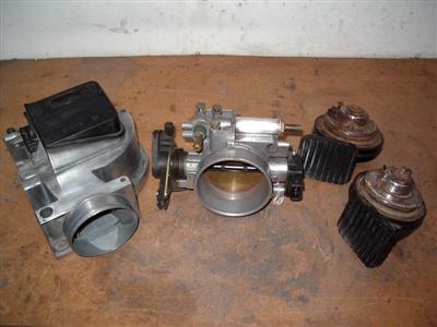 "flapper" airflow meter on the left. It uses a spring-loaded flap to measure how much air is going through it
Finally, we have that old standard, porting the head. With old engines you could make improvements yourself (I have fond memories of grinding out the ports and shaping the combustion chambers on my old chevette), but I wouldn't even consider trying to on something like this. I'm not sure what gains can be made; AHM are apparently getting 300bhp on standard heads, which sort of suggests that they're not bad as they are; but I've also had people tell me that they could do with improvement. And all the books say that cutting 3-angle valve seats are one of the best improvements you can make for airflow. So I've been put in touch with a guy who knows his way around a flow bench, and I'm going to strip down and send a head off for assesment. Wont cost much and I'll have an educated opinion on whether it's worth spending money on the heads or not. He'll also look at the inlet tract and see if that is a major restriction or not.
So my current plan is: Strip off a head, send it and the intake down to be asessed. Improve whichever is the biggest limiting factor as much as I can afford. Almost certainly swap the cams for something a bit more feisty. New exhaust. New ecu (not forgetting the cost of mapping it all to get the benefits of all the modifications).
Scuttle
So whilst all of that thinking has been going on, I was looking for something practical to do. One of the next jobs, normally, is to fit the ally sides. But (isn't there always a but), because I have the car scuttle (which is made a bit wider to accomodate the standard car GRP sides, which are quite thick), I have an overhang at each side. So I really need to fix the scuttle in position so I can make ally sides which will match up.
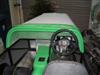
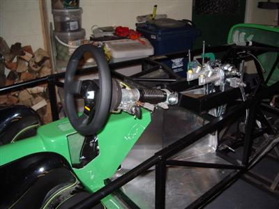
The scuttle position has to be adjusted based on where the bonnet sits, which itself depends on where the nosecone goes. The nosecone doesn't actually get fixed as standard; it's rivetted to the bonnet and "hooks" onto the chassis, with the bonnet clipped on at the rear. (I will probably make a hinge for the nosecone so that the whole assembly will pivot forwards, like several others have done). So in order to fit the scuttle, I need to mock up the nosecone, and trim and fit the bonnet. I think this will be my "filler" job for when there's nothing else on. So far I've just taped everything in place, but I think it's worthy of a pic...I really like the nose on the Rush, very "jet fighter":
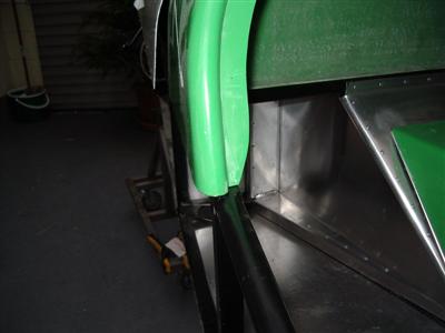
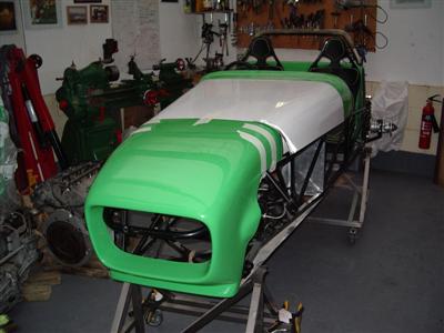 Left: showing the overhang of the scuttle. Right - nosecone, bonnet and scuttle mock-up.
Steering Wheel
And while all of that has been going on, I managed to get down to the Demon Tweaks showroom (where the staff couldn't have been more helpful I have to say) to sort out a steering wheel. (I need a steering wheel so that I can work out where the pedal box needs to go so that I can bolt that in and fix the master cylinders etc.) I wanted to actually hold the thing rather than just choosing from a catalogue...although it hasn't quite worked out...
I chose the Momo team (which is the same as Dax supply as standard), which is a nice, quality-feeling item. I went for 280mm as opposed to 300mm, which hopefully won't make things too hard. The two look barely different when you hold them together. The wheel requires an adaptor to go on the sierra shaft, which is itself a collapsable safety item. I also bought a bolt-on quick release; this goes between the adaptor and the wheel. The alternative is a weld-on one, which is (much) cheaper, but I was advised that some people had problems passing SVA (now IVA) with them. I also picked up some OMP adjustable seat runners while I was there.
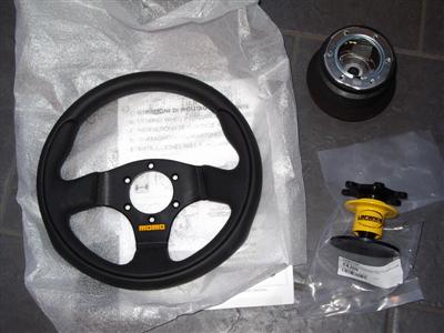
That little lot came to nearly 400 quid, ouch! Anyway, got home and tried it all on for size:
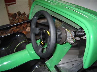 Momo adaptor; adaptor with quick release attached; and the steering wheel bolted on top
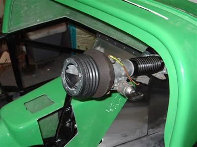
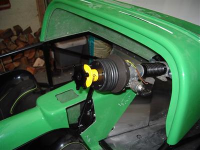
Sat in the seat and two things were apparent. Firstly, the wheel was too far back, because of the quick release. So I took the QR off, and bolted the wheel straight onto the adaptor, and it's spot on.
Secondly, the wheel is eccentric! I didn't notice until I actually attached it, but the central boss of the wheel isn't in the centre. Instead, it's offset about 15mm downwards (i.e. the rim of the wheel is offset upwards.). I guess that this is to make it easier to get your legs in. I'm really not sure if I can live with it though - it won't matter when you're on the open road, but it feels very odd to me when you do a whole turn.
It looks obvious now, but I've given it to four people and none of them noticed either, so I only feel a bit stupid. Something to watch out for!
So, I need to send the quick release back. I would still like one, but it'll have to be a weld-on job. That means, by the looks of things, removing the sierra lock gubbins from the steering column (which suits me, because I don't really want to keep the scraggy old sierra ignition lock and key anyway). No problem, except that having no steering lock means that you need a professionally-fitted immobiliser to get through IVA (because bizarely, taking the steering wheel off "doesn't count as a security device".) *sigh*
So I think that I will stick with a fixed wheel for now, and look into a weld-on QR after IVA. I'm going to think for a couple of days, but I will probably swap the steering wheel for something which is actually circular. There aren't many to choose from in the smaller sizes, and many of what there are are eccentric, but there are a couple.
21 January 2010
Two updates in a week, unheard of for me! I seem to be doing odd bits here and there rather than working on a single thing at the moment, so this might all be a bit hard to follow...
Firstly, I spent a few days playing with the steering wheel mounted on the car, which is (a) kinda fun and (b) has convinced me that the eccentric thing isn't actually going to bother me. Once over the initial surprise, I decided that I'll be quite happy with it. Apart from that, it's leather, and the only other options are suede, which I don't think will be so good when it inevitably gets wet.
Secondly, spent some time playing with the position of seat, wheel and pedal box. I bolted the master cylinders temporarily in place so that the brake pedal would assume its proper "at rest" position - I'm assuming that the others will be similar. As it turns out, I want the pedals to be as far forwards as they'll go - 85mm from the front of the mounting bracket according to the manual. Ideally I think I'd move them forwards very slightly, maybe 20mm, but then you start eating into pedal travel. Shouldn't really be an issue.
Engine - Head Removal
Finally, I started stripping down the engine - aiming to remove a cylinder head so that I can get the tuners to look at it. I'll do step-by-step pictures because, despite having the workshop manual and everything on the internet, some things are still not obvious when you get to them...
I'm stripping off the driver's side head. First off is to remove the ignition coil packs. These are held in by four bolts each, then just pull out:
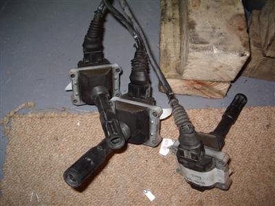
Look in pretty good condition overall, but the rubber wire cover have perished and will need replacing. The wire connectors are held on by a "c" shaped spring wire - I levered this open with a screwdriver and they slide off easily.
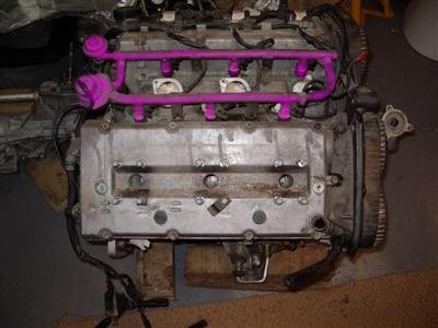
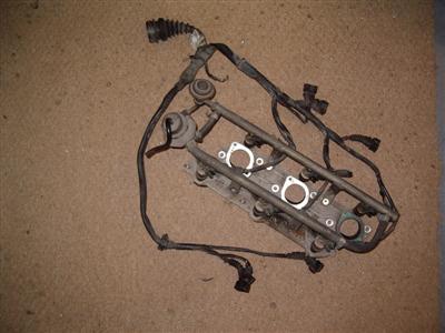
Next, the fuel rail and injectors (below in purple) should come off according to the manual. The rail is held on by four bolts, and it looks like it should just pull off. It didn't though, and I was unwilling to force it. So I took the easy way out, and unbolted the two injector manifolds from the heads. The whole lot came away easily.
Couldn't find much info on removing injectors, but a bit of internet browsing suggested that they should indeed pull out, and in fact you can buy a levering tool. I cheated and used a suitable spanner to lever against the body of the injector. I imagine it's pretty important not to push against the end of the nozzle. One of them was rather tight, but the rest came out ok with a bit of WD-40 and gentle easing. Turns out that they are just held in by a tight-fitting rubber o-ring.
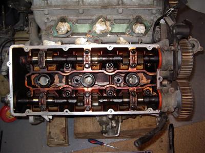
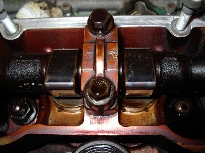
Then it was off with the rocker cover (probably called something else on OHC engines, but it's a rocker cover to me). Nothing untoward looking inside. Some scuff marks on the lobes but that's to be expected, no visible wear apart from that though.
Normally you'd take the cam pulleys off about now - I'm leaving them on because I imagine that the tuners may need to rotate the cams. I'll need to check if that's right, or if I need to take them off.
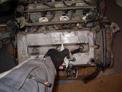
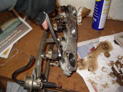
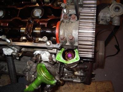
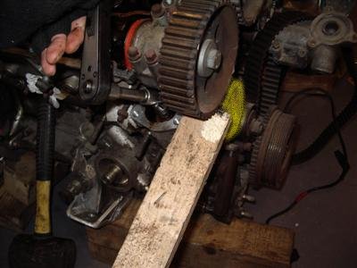
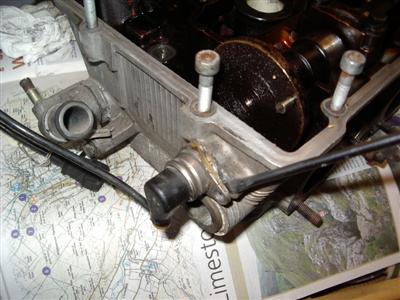
Final step before removing the head is to take off the oil pump drive cog. This isn't on newer models, it was on 12v and early 24v V6s. The cover is removed (green) to reveal the nut which needs to come off (purple). You need to prevent it from turning - there is an alfa tool for holding the drive pully (yellow) still. I just used that old standby, a length of softwood. The cog should then pull out - I couldn't get it out though, so I just left it disconnected.
That done, it's off with his head! Head bolts were of course tight. An extension bar solves that, but I had to sit on the engine to stop it moving whilst I undid them. Working up a sweat in the garage is an unusual thing at this time of year!
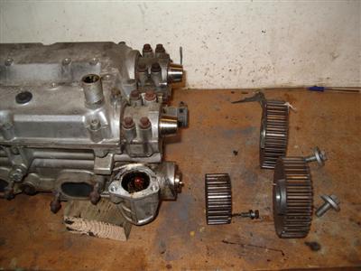
The head was a bit reluctant to move even with the bolts undone, but a few taps with the rubber mallet persuaded it upwards. The oil pump cog lifted out with the head, and was then easy to remove (below, right)
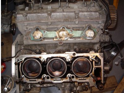
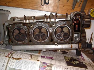
Again, everything looks in good condition. The cross-honing on the bores is still very visible (below, left), pretty good after 150,000 miles I'd have thought:
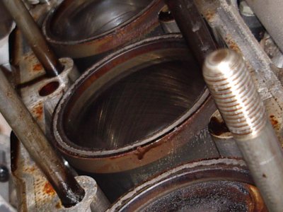
I need to fasion some holders to keep the piston sleeves in place - they're prone to falling out if you're not careful, the normal thing is to bolt some big washers or steel strips across the top of the block.
Final job for the night was removal of the cam position sensor from the head. A single bolt, then pry it out gently:
09 February 2010
Not too much done because I've been away snowboarding - well you can't be in the garage all the time.
What I did manage is to make some panels to close off the pedal box - took a couple of goes getting these right, because everyone has their bonnet off at car shows, and the pedal box area is highly visible. The panels are riveted and wurthed into place as normal. I think I will machine up some nice stainless spacers to go either side of the throttle pedal bearing to replace the washer stacks that are there currently, another filler job.

For now, I'm more interested in getting the scuttle position sorted. With the pedal box in place, you need to cut a quite large hole in it to clear the master cylinders. A dished panel is supplied to cover over the gap - and this itself needs trimming to fit neatly around the pedal box brackets. You can see it in the pic above. Seems as if it would be better if the scuttle moulding just had this dish in it, but whatever. For now I've cut the scuttle hole a little small, it will need tidying up later - probably with some edge trim to hide the cut edge of the GRP. Again, for now I'm just interested in the position of everything. Next job is to work out some hinges for the nosecone and get that attached, then I can attach the bonnet and from there see where the scuttle will go.
On to the engine - had another chat with the tuning people, and the upshot is that I'm going to send the head, inlet pipes, plenum, and throttle body. They also want the cam pullies removing, so I popped them off.
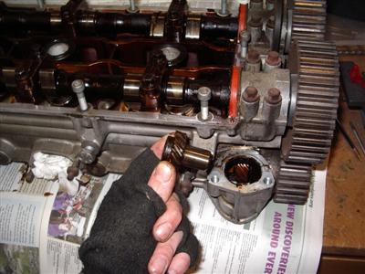
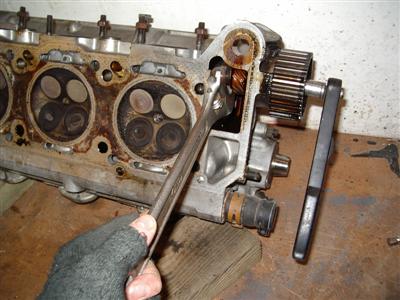
There is a special tool to hold the pulleys whilst you lossen the bolts - I just stuck a bit of mild bar through the pully holes so that it wedged against the side of the head, and that held them whilst I undid the main bolts. After that, I gave them a couple of taps with the rubber mallet and a softwood drift, and they popped off the tapers easily:
The smaller pully is for the oil pump. There is yet another special tool for this, and it's a bit more tricky to stop it from moving. Fortunately, the other end of the shaft is just accesible from inside the head, and has a large bolt on the end. I was able to get a large spanner in to hold it still, whilst using a socket on the pully bolt:
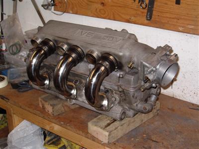
Then it was just a case of bolting the plenum, intake pipes, and throttle body together. I had to remove the old intake pipes from the plenum first, so I had a good look at the difference between them and the larger 45mm (GTA/Cloverleaf) ones I'd bought.
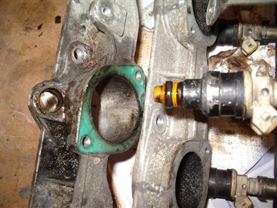
The ports on both the plenum and head match the bore of the larger pipes; the smaller pipes are flared out at the head end to match. At the plenum end though, they are just smaller, with the rubber connector bulging out. This creates a huge step for the incomming air to negotiate - no wonder they sap power!
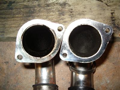
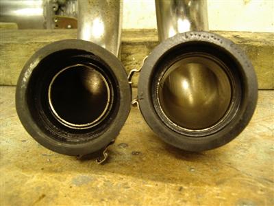 Left - the head ends. The smaller pipe (left) is flared to match the inlet port. Right - plenum end. No flare or taper here, the rubber connector just steps down to the size of the smaller pipe. Yuk.
With the whole lot bolted together, I now need to pack it (somehow) and arrange a courier. It weighs in at 31kg, so I'm thinking I need to knock together a wooden crate or similar.