
Brake Lines and Other Bits
23 June 2009
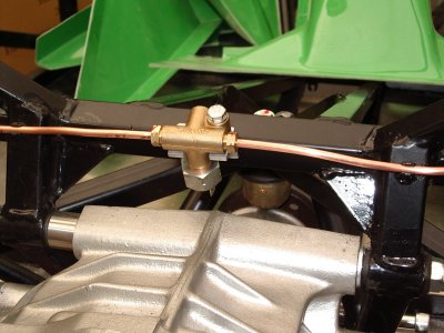
So the next job in the build manual is putting in the copper brake lines. The first thing suggested is to fit the rear union where the lines branch to go out to each wheel, and also holds the brake light switch. As shown, this is just bolted to the chassis with a self-tapper (yuk) with the switch uppermost.
There are two problems with this; firstly, it fouls on the rear bulkhead. Secondly, I've seen several people pointing out that, with the switch upwards, it could cause a pocket where an air bubble could get trapped, leading to spongy brakes. So I decided to fit it with the switch pointing downwards. It means that the wires for the switch might be a bit less accessible, but on the plus side the connection for the brake line going to the front of the car will be facing the right way.
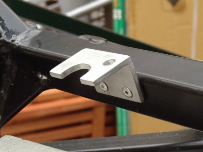
This requires a custom mounting bracket, which I made out of some ally angle I had. Took a surprisingly long time to get it the right shape, but it makes a neat job. I rivetted this to the chassis, with a bit of wurth to prevent moisture getting into the holes.
Then you run the copper lines out to a support bracket above the shock mounts, where they join the flexible hoses which go down to the callipers. The tube can be bent by hand, using sockets or bars as formers where required. They are clipped to the chassis using supplied plastic clips - you drill a hole and they just push in, although I put a blob of wurth on each to prevent rust.
All good in theory. However I made a slight mistake, in that I lined my union up nicely between the two diff brackets. However, these are actually slightly offset from the centre of the car. So it looks right, but meant that one of my copper lines only just reached...one to watch out for. Although it's fine, it means that the brake run on that side isn't as neat as I'd like. I've also been talking to people about brake lines generally (hat-tip to Twobad!), especially where they are visible in the engine bay, and have decided to get a proper bending tool so I can make a better job of it. I'll get some more pipe and a flaring tool while I'm at it - I think I'll put in some connectors just before the pipes will be visible, then I can have several goes at doing the visible parts nicely without needing to redo the whole run each time.
Making the visible lines separately is a damn good idea! It saved me a lot of pain later on, when I had to remake the brake lines in the engine bay!
I used Cunifer brake pipe rather than pure copper, as it's generally regarded as superior and with a longer service life. However, it is much harder to flare, and I had a lot of leaks when I came to fill the brake system. My Brake Flaring Page goes through the problems and what I had to do to solve them.
So that meant I was stalled on the brake lines for a bit, and I had a (rare) whole day in the garage. So I thought I'd have a look at the rear bulkhead.
Before the bulkhead itself, you have to fit the corner pieces. When I came to it however, the finish on both of them is very poor - there are lots of holes in the gelcoat, maybe airbubbles? Anyway, I will talk to Dax about it. So that meant I couldn't fit them yet; I did however trim the rear bulkhead (finish is fine on this piece) to fit so that it's ready to go. I used a dremel with sanding drums to just "stroke" the edges to the right shape, which seems to work pretty well.
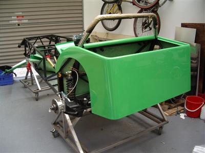
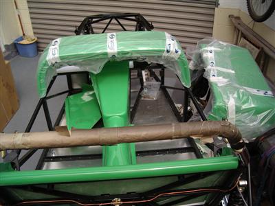
With that temporarily in place, I had a go at test fitting the steering column, pedals, transmission tunnel, rear body and scuttle, to get a feel for where everything is going to go. It's quite hard to visualise how it all fits together when you're just looking at a bare chassis, particularly around the scuttle/dash area. This took a good few hours, what with getting things out of the attic, unwrapping, re-wrapping etc, but was a very useful exersise. Took lots of pictures so I can refer to them later, here's a couple:
Soon I will want to trial fit the engine and box, so I can work out what happens at the front of the transmission tunnel in terms of clearance, and whether to go with the GRP footwell panels or make some ally ones. Can't do that yet as I am still waiting for my gearbox mount...
Throttle Pedal Modification
So I was reaching a bit of an impasse; then I remembered a forum discussion about the standard accelerator pedal - a few people have had scary moments when this has got stuck. As standard, it just pivots on a rod, and is held in with a couple of nuts and some washers. A common improvement is to press a 608 bearing into the pedal to stop this happening.
608 bearings are commmonly used in electric motors and skateboards, so easy to get hold of, about a pound a piece - your local skateshop will be able to sort you out.I happened to have a few in the loft, so I thought I'd set about modifying my pedal.
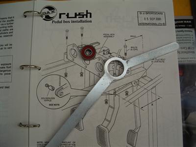
The existing hole needs taking out to a nominal 22mm - I did this with a tapered hole cutter from both sides, then very carefully used a fine file and emery paper to take it out until it was a press fit (using a vice) without crushing the bearing. That all worked well, but a "wiggle test" (put pedal on shaft, clamp shaft in vice, wiggle end of pedal) showed that, with enough side loading on the pedal, it could eventually work it's way off of the bearing; really the pedal is a bit thin to hold the bearing in with just a press fit. I considered various schemes of using dished spacers, or bonding the bearing in, or even making a new pedal with double bearings in, but eventually decided that welding it in would be a lot quicker and easier, and hence worth a try first. Easilly done with the MIG, just had to be very quick so as not to distort the bearing itself.The finished article now turns nicely on the bearing and passes the wiggle test with flying colours!
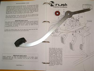
 Left - unmodified pedal and bearing. Right - 22mm hole cut into pedal
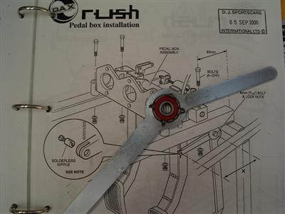 Bearing welded in place
25 June 2009
Back to the brake lines...my tools and pipe arrived, so I set about re-doing the brake lines I'd just done. Had a bit of of practice with the flaring and bending tools first, it's very liberating suddenly to have some spare pipe and to not have to worry about getting it right first time. Even with the right tools, it still took ages (particularly as the handle of my bending tool snapped and I had to weld it back together), but I am much happier with the finished result. Having my time again, I'd just not bother buying the brake line kit and make it up from scratch.
I also spoke to Dax about the two panels, and they're going to make me up some more, and send them up along with my gearbox mount.