Rolling Road Booking
2nd October 2013
With the engine now running ok (I think!), my goal is to get it rolling roaded as soon as possible - from then it really should "just" be a dash to IVA.
I looked at a local place, but they'd never dealt with Emerald ECUs before, and while happy to "have a go", I didn't really fancy that. After a bit more looking around I thought that I may as well just bite the bullet and go to Emerald themselves. They've got a great reputation and I've followed "Walker's Workshop" through the magazines for years. So I'm booked in for the middle of October. I've managed to borrow a trailer and hired a van to tow it with, so there's just the slight matter of a 5 hour journey never having towed before.
So between now and then, I'm focussed on doing the things needed for the RR session. Getting the sides on properly, hopefully finally this time. Sorting out the air filter and wiring around the battery. And getting the bonnet catches installed so that I don't have to tape it all down for the journey again.
Air Filter / Wiring
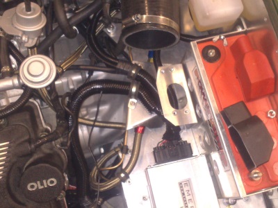
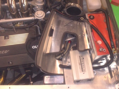
I've been faffing with the layout of things on the battery shelf for what seems like ages. As mentioned before, the previous air filter bracket didn't fit so well with all of the wiring, so I came up with a new design. One of the biggest problems was all the wires - it's a bit of a rat's nest with the ECU harness, main battery wires, fuel lines, and starter motor wire all crossing each other in the same 2 square inches. It's a good example of something I could have planned out better, if only I'd have known what I was going to end up with. It's hard to visualise 2 years before having the wiring in what it will end up looking like.I made one support/cover type affair, which was ok, if a bit messy, but eventually had to admit that the starter lead just wasn't quite long enough - shame as it was a good quality affair from the donor. Anyway, I made up a new longer one from 300A cable and it gave me a bit more leeway.
So the final set up is a kind of layered set of covers all made of 1mm ally, the first of which covers the fuel filter and acts as a support for the ECU harness, keeping fuel pipes and wiring separated:
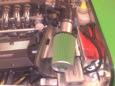
Then there is a curved shield which firstly acts as the side of the bracket, and secondly, should give the filter some shelter from the heat of the engine bay:
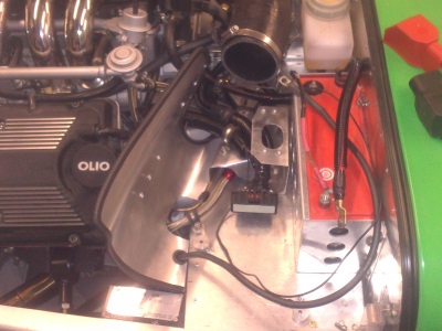
Then the shelf which supports the air filter, as well as hiding the messy wiring. The main battery earth cable goes under the ECU which I have raised up on little ally spacers. This was actually mainly to give the ECU harness a better run, with space for the earth cable a bonus.
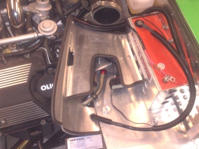
And finally, the air filter sits on top, quite well secured by the shape of the shelf. I've managed to get the battery cables reasonably neat and away from all of the other pipes and things, so pretty good considering.
And with that done, I could look at cutting some vents in the bonnet to get some cold air to the filter...
Bonnet Vents
I'd been playing with various designs for a while, and looking into NACA vents and scoops and things, with lots of cardboard cutouts and tape. But ultimately, space is so limited, and the shape of the bonnet so curved above the filter, that short of making a custom scoop to match the custom bulge, there was nothing I could get to fit. So instead I decided to go for the simple "cut outs in the bonnet" approach, which to be fair I prefer the look of anyway. I dare say it's moderately less efficient than a NACA duct, but then probably more aerodynamic than a scoop.
So then followed more cardboard cutouts and tape until I had a design I was happy with. It's actually a copy of one I've seen on another Rush some years back and really liked - a set of slots with circular ends, staggered backwards and working around the curve of the bonnet.
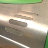
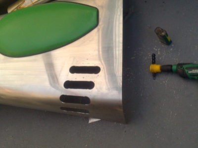
Simple enough to cut out - I used a hole saw, then the power nibbler (caaaaaarefully!), and a file and emery paper to finish off.
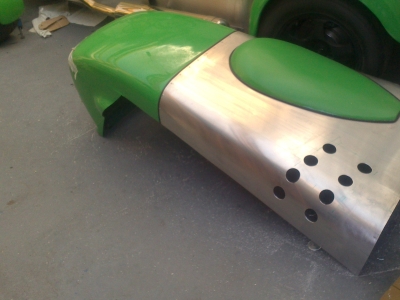
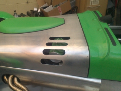
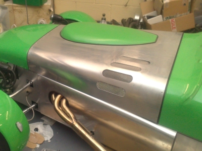
Then a bit of mesh fitted - bonded on using wurth:
The important thing I found here, and which took some considerable experimentation, is that the alignment of each slot has to match an imaginary line which follows the curve of the bonnet to an imaginary point in front of it. If they all line up parallel, it doesn't look right. So I divided the front and back of the bonnet into a number of points - using the rivets at the front as they were already there and equally spaced. So then mark the same number of points on the rear edge (which of course are further apart). Then draw lines from front to back between each pair of marks, and that gives a set of alignment lines down the bonnet, and the slots are aligned with these. It's hard to make out in the photos, but like this:
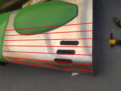
You get the idea.
Bonnet Catches
22 October 2013
A lot to report and much still to do, so just a quick entry for now
After the vents, I was keen to get the bonnet catches done so that I didn't have to tape it down for transport. I elected to use Aerocatches rather than the default over-centre things, especially since you need to use rubber ones to get through the IVA. Just under 50 quid for the pair, so not cheap, but well worth it I think.
The catches have a metal rod which attaches to the chassis, and the catch itself which attaches to the bonnet. I had the flush-fit type which meant that I'd only have one chance to get the bonnet hole for the catch right. So I elected to do these first, then put the rod on a moveable base so that I could fine tune the fit - which is what production cars do after all.
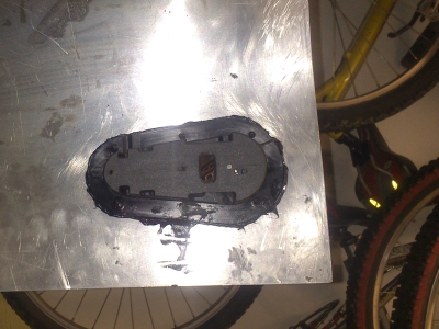
Fitting the catches was easy enough - careful, slow cutting out of a hole with the power nibbler, and filing to shape. Then the catches were bonded in with Wurth. Below is the catch seen from the inside of the bonnet:
Fitting the rod was harder. It's a 10mm threaded aluminium rod with a flattened end with a hole in, into which the catch latches. I didn't fancy drilling a 10mm hole in the chassis member, so I made up a flat plate with a threaded boss to screw it into. The flat plate had slotted holes so that I could move it around to the correct position. I removed two rivets from the chassis rail and threaded the holes to M5, so that I could screw the plate down. With a bit of fettling (enlarging the slotted holes in the required direction using a dremel, until they were right), I finally got them in the right position, so that the catches engaged and held the bonnet firm. Then I marked them up, and for the final fitting, wurthed the plate down to the to of the side panel, as well as the two bolts. So it's basically bonded to the side panel, which itself is bolted to the chassis rail. Picture below shows the setup:

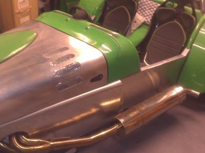 It's hard to see the edge of the side panel, so I've highlighted it in purple
This has turned out to be plenty strong enough, without having to drill any more holes into the chassis rail.
System Check
So with everything done, I wanted to check a few things. I'd done a few other bits, such as refitting the bottom of the dashboard which hadn't fit properly since I'd finally fitted the tunnel - the addition of foam strips on the bottom had raised the tunnel up a few mm. So I removed the gauges and filed the bottom of the dash down a little, then added a trim strip before refitting it all.
With it all back together, I fired it up. It went, but for some reason the gauges weren't working. Well I'd not connected the tacho, so that was easy. But I'd connected the others backwards - signal to where the +12v feed should be, and vice versa. Reconnected and they still didn't work. Surely I couldn't have broken them just with a few seconds being connected backwards?
Much investigation ensued. All the electrics looked right, I had 12v where I should, and I could see the sensor resistance values changing when I ran the engine. With little time left, I figured that I could live without them - but I did fancy an oil pressure gauge to keep an eye on on the rolling road. So I plumbed my mechanical test gauge in so at least I'd have something.
I also noticed that I'd not tightened up the main alternator bolt! Ooops. While I was doing that I also noticed that I was missing a washer, so the alternator was a couple of mm too far back, and the belt was very slightly out of alignment. So easy to miss stuff like this.
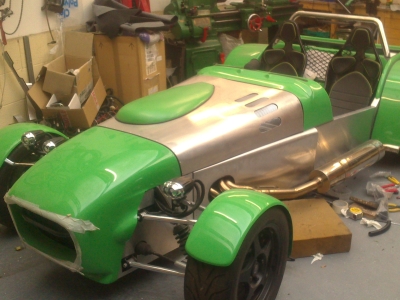
Next issue - check that the car would go down our rather steep drive. I'm happy to report that it did, with an inch or so of clearance. A brief road test around the close ensued, whereupon I found that I had a 10A Fuse for the fuel pump instead of 15A. I found out because it kept blowing and bringing everything to a halt. Rather stressful for a while until I found out what it was.
I also found out that the driver's side indicator fouled the wheel arch on full lock. I found out because it broke off when the fouling took place. Bum. Something else to fix.
And with that, I was ready to go, with one evening to spare.
Gearstick Gaiter
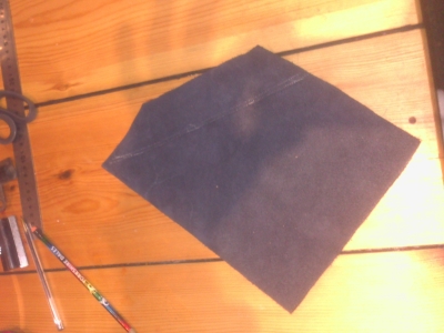
I wasn't really planning to do anything the evening before, but I started looking at the small piece of leather I'd bought for the gearstick gaiter and wondering how I might make it, and before I knew it, I'd actually done it. A rare easy success:
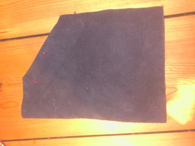 Left - work out how to fold to make a cone, note edges turned in to make an internal seam. Right - turn inside out and pin.
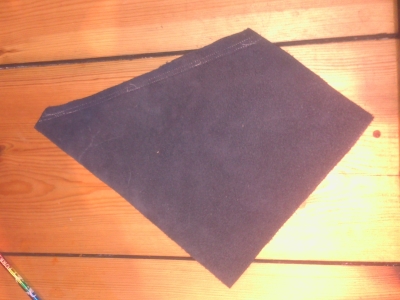 Borro the Missus' sewing machine and sew the seam, then trim off the excess
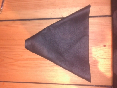
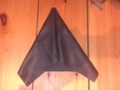
 Turn back the right way out, and behold, a leather cone! Clamp to the base plate to check fit, trim off the excess, make holes for the bolts.
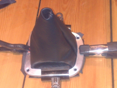
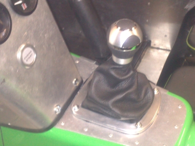 Fitted and in place. Need some countersunk bolts but otherwise, all done. Shame about the crappy photo.