Propshaft Fail
15th May 2012
In between buck and mold making, I was persuing various other avenues. The main thing was a propshaft and speed sensor - with those two bits in, I would be able to finally bolt the transmission tunnel down, which will in turn allow me to get a whole load of other stuff fixed down.
So I measured up and ordered one. Then waited....and waited...and waited. It eventually came after about 6 weeks of being told it would be ready in a week...sadly not an uncommon experience.
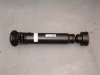
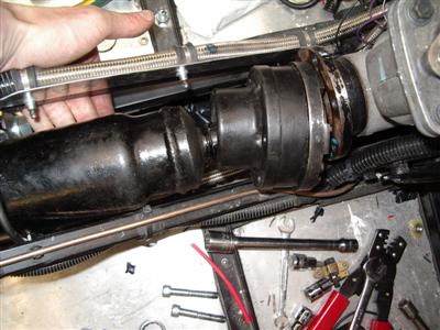
Then it arrived:
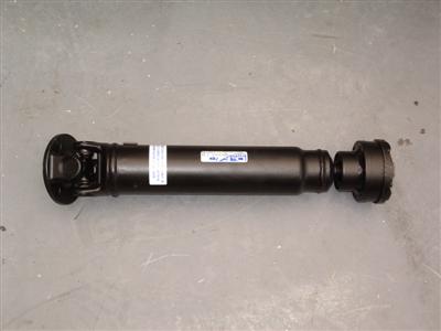
The first problem I had was that I couldn't get it into place. The flanges are too wide to lift or lower it in vertically, so it had to go in from the side. Unfortunately, I'd welded a support in to hold the propcatcher, and it was right in the way. So that had to be cut out and ground away - there's still one on the other side though, which I suspect will be enough on its own.
So after all that, I manouvered it into place and...it's about 20mm too long.
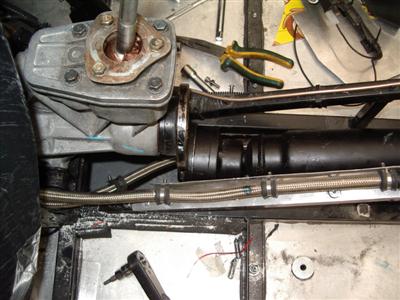
Tits, sod and buggery.
How on earth could this have happened? I whipped out the rule and remeasured the gap, and lo and behold, it's 10mm shorter than the measurement I'd ordered. I think that maybe I'd hooked the tape measure over the back of the flange, rather than holding it against the mating face. Then I measured the shaft and found that it was nearly 10mm longer than the measurement I'd ordered. So it looks like I've fucked up, and then they've fucked up on top.
More annoyingly, there's about an inch of extension in the shaft, so if they'd made it so that the nominal measurement was in the middle of the play, it might just fit. But no, it's done so that it could go longer, but not shorter, than the specified length.
So all in all, pretty hacked off, not least with myself. I'll need to send it off and get it shortened. No biggy in the scheme of things, just more time and money...
Speedo and Column Cowl
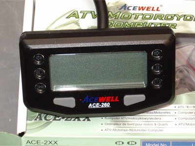
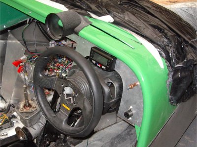
I'd chosen a speedo some time ago - an Acewell ACE digital unit, which also includes the mandatory warning lamps needed for IVA. It's small enough to fit above the steering column, which is what I was after. Although in the main I prefer analogue guages, the space behind the wheel is rather small, so I think a digital one will be clearer.
I'd also decided that the sierra cowl didn't really work with the speedo, so I'd looked around for something else. Eventually, took a punt on one from an MX5, which arrived and fortunately was just about the right size and shape. It did need a bit of chopping to get it to fit, but nothing too major. The section of dashboard needed a bit of trimming and some of the old hole filling in - since this bit will be covered, I can get away with that quite easily.
Speaking of which, at stoneleigh the other week, I'd finally succumbed and bought one of the drill-driven nibblers which is on show every year, and this was my first chance to use it. Superb little tool, did the job in seconds. I really should have bought one at the beginning, it would have saved me hours.
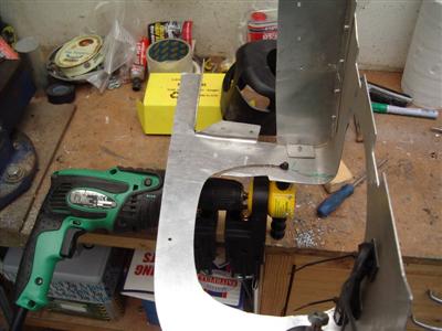
I also needed to make a bracket to connect the new cowl to the column. A piece of 1.5mm ally did the job, with a couple of nuts bonded to it with araldite to take the 3 bolts which hold the cowl on
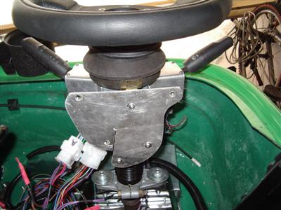
Then a quick mockup to check that everything fits...
Then a bit of fiberglassing and filling to cover up the resulting gaps, and the hole for the key. I'll give it a coat of crackle black to match the engine and guage pods on the dash.
Speedo Wiring
14th July 2012
While I was waiting for the propshaft to be sorted out, I figured I'd get on with wiring in the speedo, since it was there. The speed sensor will go on the propshaft, so I needed to get that bit worked out anyway.
The speedo also has 6 warning lights on it - indicators, brake, lights, main beam, fogs. The dax loom provides outputs for all of these, although I'd already hacked most of them about to put additional relays in etc. I also needed to put in an additional run of wire for the brake test switch (normally this is a microswitch on the handbrake, but there's no room for it in my fitment), and the speedo needs a constant live feed for the clock. The indicator wiring has changed as well, because my LED indicators mean I'm having to use an electronic flasher instead of the supplied bimetalic one. So it was a bit more complicated than just connecting up the right wires, and took a few evenings to do.
As an aside, I was a bit concerned that the lights on the speedo might be a bit cheap looking, but I'm happy to report that the unit looks rather smart.
I got all of that finished in time to go on holiday for a week. Now it had been raining for weeks, but the week we were away was the week of epic flooding, golf-ball sized hailstones in some parts of the country, and general weather-related carnage.
So when we returned, it was to find that there had been a certain amount of water-related ingress. The roof had leaked and water had run down the back wall, soaking everything on the floor. It had also got into my box of lathe tooling (fortunately heavily oiled so got away with that). The rain then continued for another week, which meant that I couldn't do much about it except carry on mopping it up. I also had to unpack a shedload of stuff and spread it out to dry. Bit of an arse, though things are pretty much dry now (2 weeks later), and I've (hopefully) fixed the leak.
Propshaft and Prop Catcher
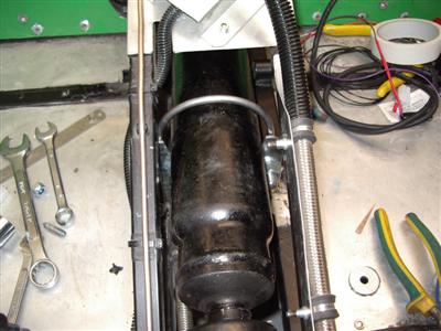
A nicer thing to return to was my shortened propshaft. And this time it fits, yaaaay. But before I could just bolt it up, I needed to make a prop catcher.
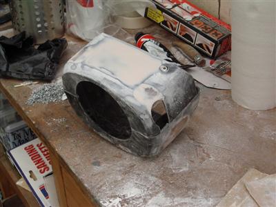
The first thing I noticed is that the shaft is very fat, and there wasn't really room to make a simple 2 piece catcher out of 3mm plate - it would be too thin around the sides. So after a bit of playing around with card templates, I decided to make the bottom out of plate, and the top half out of 6mm steel bar.
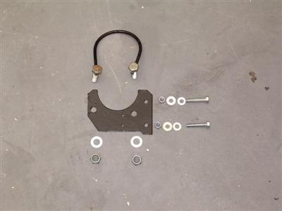
I bent the bar around an empty welding gas canister which was a convenient size. It's held onto the plate by two M12 bolts, cross drilled so that the bar slots into them. It's not as big and hefty as I'd originally hoped, purely because of the lack of space in the tunnel.
A few tests to see how much it could move with each end disconected showed that it can't reach any of the brake or fuel lines, and I gave it a good whacking to see how solid it felt. Better than I expected, it feels very solid, though I'm under no illusions that a bit of manual waggling is anything like as big as the forces which can be generated if something like this breaks.
That said, I think it will probably be strong enough to buy me some time should the worst happen. It fits nice and close to the shaft so any forces from it flailing around should be minimised. Even if it only stands up for 10 seconds, it's worth having.
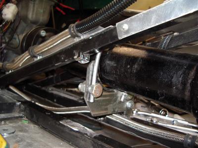
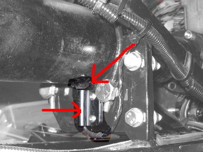
The catcher also provides a convenient bracket for the speed sensor. This is a reed type, which works by sensing a magnet glued to the propshaft. I glued the magnet on with plenty of Wurth (top arrow), and the sensor simply bolts to the catcher (bottom arrow):
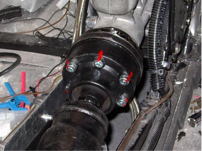
Then it was "just" a case of bolting the propshaft in properly. Of course, this means jacking everything up so that the wheels (and hence the shaft) can turn around freely, so you can get at all the bolts. Then putting it in gear and using the handbrake to hold the shaft still while doing each bolt up.
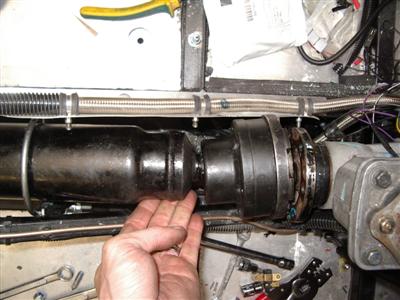
I've used the standard ford bolts for the ford end, and 12.9 M8 for the honda end (same grade as for the driveshalf flanges). I didn't have the torque figure for the honda flange, so I've used the same as for the ford - I can't imagine they'd be vastly different. Plenty of locktight on each, and finally, marked with red paint lines so that any movement will be easily visible:
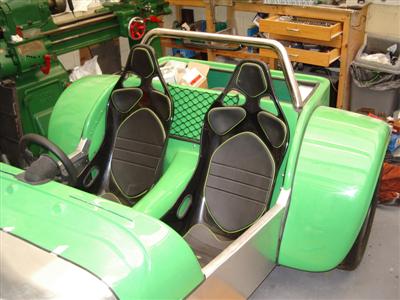
With everything in the transmission tunnel finished, I could finally bolt the tunnel moulding on for real, and get the passenger seat in. The tunnel fought me all the way, for some reason - everything I'd carefully measured and trial fitted seemed now to be 3 or 4 mm out, just enough so that none of the bolt holes aligned properly. So there was more fitting, filing, and generally fettling until the thing finally went in properly. But go in it did, eventually. I needed to hoover the cockpit area out first as it was full of garbage by this time.
With the tunnel in place, I could also bolt in the passenger seat (though soon after I did, I realised that I'll probably have to take it out again as I want to fit some carpet panels). But before that, I bolted in a cargo net pocket behind the seat for a bit of handy in-car storage:
Next Steps
My thinking currently is that I'll look at doing the bonnet bulge next, and carry on with various wiring jobs as a filler task. Then I'll start investigating getting the exhausts done.