So Then...
9th October 2011
Things, by which I mean me, are a bit happier this week, as I've sorted some of the problems out. Firstly, the Catcams people assure me that the pulleys can be machined down without weakening them. So I've posted them off to be machined - I could do it myself easily enough, but for the money they cost, I'd rather they did it - just in case I cocked it up.
I sent off for an alternator and some chunks of steel to build a bracket out of (of which more below). Whilst I was waiting for that lot to arrive, I did a few engine bits.
Heads on
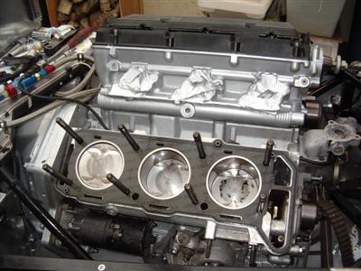
Now I was happy that the pistons aren't going to crash into the valves as soon as I start it up, the heads could go on for real. I made sure I fitted the camshaft position sensor into the driver's side head before putting the head on, as space is rather tight back there. I sealed it in with some silicone as per the manual, and it's held in with a single bolt.
I gave the head mating surfaces a final clean, put the gaskets on, and on went the heads. The last time I'll see the pistons, hopefully - at least for a few years.
The headbolts are each torqued up to 25Nm, then turned through a further 240 degrees, which equates to "properly b*****d tight". A long breaker bar essential here!
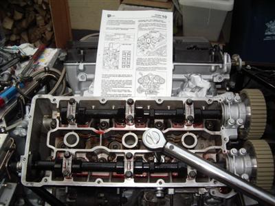
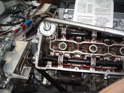 Note page from the manual so that I get the tightening order right!
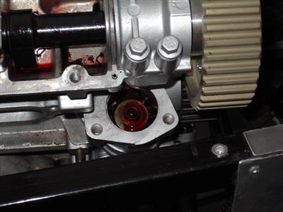
The oil pump drive cog and cover can then go on - easy enough, though the screw thread on top of the drive shaft is rather small and delicate - I was a bit worried about how tight to do it, but I've locktighted it to be on the safe side. The cover had a flat washer in it, which looked rather perished. The head gasket set I had didn't have a spare in, so I discarded it and replaced with sealant. A gave it all a good splurge of assembly lube before screwing on the cover.
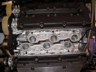
So that was that. Until I get the timing gear on, I can't build much more above the heads, as it'll all have to come off to time the cams in. I'm not sure if I should leave that for a bit - dunno if the belt will take a set if it's sat for several months without moving. Something to look into. So the last bit for now is the small inlet manifolds which hold the injectors. These bolt straight to the heads - since they'll be permanently fixed, I used "hylomer blue" sealant on the mating faces, which is a fuel-safe sealant. (silicone isn't safe for exposure to petrol). I cleaned and painted them first, to match the heads.
Exhaust Manifolds
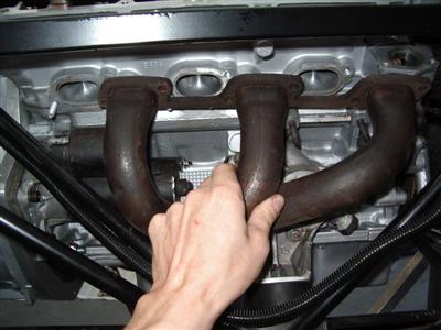
One thing I wanted to check before I went any further was whether there was any chance of making the standard exhaust headers fit. I checked, and the quick answer is, there isn't. So custom it will have to be.
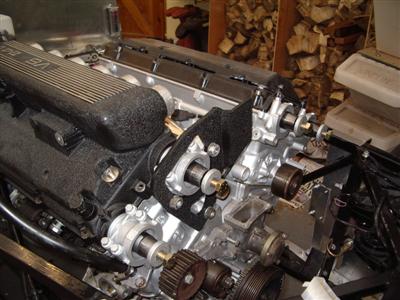
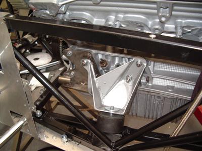
Top Pulley Support / Engine Stay
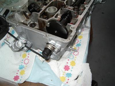
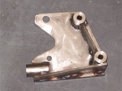
There's a large bracket which bolts to the front of the driver's side head, which supports the central timing belt pulley. It also holds a large bushing (arrowed below), which on the donor car was attached to a tie rod attached to the chassis by a large rubber. This prevented the engine rotating under its own torque.
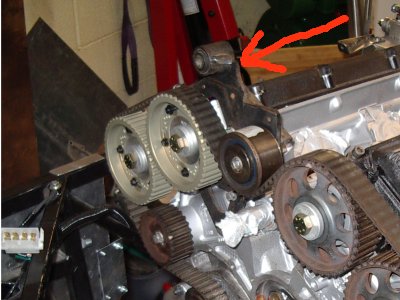
This would of course be very useful to me, since I need to restrict sideways movement to about 10mm each way. Alas, the bushing is mounted very high, and would be out the top of the bonnet. So it had to go, and I'll have to fashion a replacement somewhere and somehow else.
Two minutes with the angle grinder and it was off. I then painted it up with the same crackle black paint I'd used for the engine covers, and on it went.
Alternator
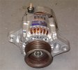
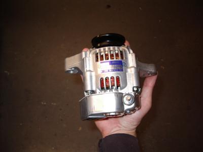
So at last to the alternator. I ordered a Denso 40amp model, which seems to becomming established as the darling of the kit car world. They are sold in various places under various guises - Demon Tweeks and the like sell them as "lightweight racing" models, they are used on Kubota tractors, or can be found being sold directly under the Denso name.
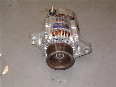
Their popularity is easy to explain when you get hold of one - small enough to sit in your hand, and weighing in at 2.8Kg, they really are tiny. Mine is shown below, with the one from the Alfa donor for comparison:
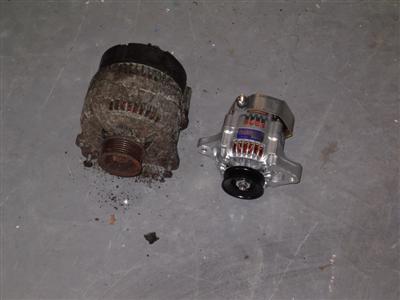
The original is also much, much heavier - my scales only went up to 5Kg, and it was considerably over that - I'd estimate maybe 7? Probably 2.5 times heavier than the denso anyway.
So I needed to build a mount, but before that, I had to do something about the pulley. The alternator comes with a single v-pulley, but the alfa engine uses a flat poly-v belt. So I needed to fit the pulley from the alfa alternator to the new one.
The pulley came of the alfa alternator easily enough, but removing the denso one proved a bit more difficult. The problem is that the shaft freewheels, so you need a way of holding it still while you undo the nut. The shaft is machined to take a 10mm socket, so you need a box spanner to undo the main nut, with a normal 10mm socket down inside of it holding the shaft still. There are special tools for this, but you're looking at 40 quid or so.
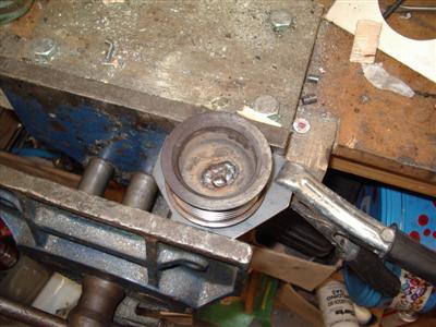
So instead, I bought a cheapy set of box spanners for a fiver, and welded a bit of pipe to one to make a handle. Unfortunately, the main nut was on so tightly that all I achieved was stripping the 10mm flats on the end of the shaft. Hmmm.
This left me a bit stuck, so since I was going to discard the pulley anyway, I ended up just gripping it really tightly in a vice, and getting a 2 foot breaker bar on the nut. Which worked, though it did graunch the pulley a bit. I dunno what they put that nut on with, but they don't want it comming off, that's for sure! I'm not a fan of such brutality, but sometimes it's the only way...
So that done, I could see what I was dealing with. First problem, the mounting hole in the alfa pulley was about 2mm too big; and secondly, it was too thick. I had a bit of a ponder, and figured that I'd weld the hole up and turn it to the size I needed on the lathe.
To weld it, I sat it on a bit of 3mm plate, and just puddled molten metal in the central hole until it reached the top. Then sawed it off the plate with a hacksaw.
Boring the central hole to the right size, and thining the face down in the lathe was then very straightforwards, which made a pleasant change! Final result, one Denso alternator with alfa pulley:
Next job, mounting bracket...
Alternator Bracket
21 October 2011
Various parcels of metal offcuts arrived over the next few days, and I got down to making the bracket. I decided to use 4mm stainless plate for the base of it - maybe a bit thick (the engine mounts are 3mm mild steel), but it's not going to have much triangulation, so I erred on the safe side. I'm using stainless because, as mentioned, I HATE RUST! I don't think there are any particular metalurgical reasons why it wouldn't be suitable for this, but then I don't know much metalurgy. S'metal, innit?
I started by cutting a base plate to fit over the studs on the engine block. Easy enough, though one of my holes was about a mm out and I had to enlarge it with a file. This always seems to happen, I think it's my cheap wobbly pillar drill and lack of proper clamps which is to blame.
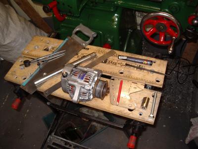
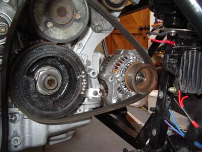
Next job was to turn up a bit of round bar with a hole through to form the actual mounting. With the pieces done, I bolted the plate to the engine, and could offer up the alternator to see exactly where it needed to go. This all took place over a number of nights, each time requiring that I lifted the engine and remove the engine mount. So a bit of a faff.
It's hard because there's no obvious reference plane you can use. I settled for holding a straight edge across the front of the waterpump pully, and lining the front of the alternator pulley up with that. A bit fiddly since I needed one hand to hold the alternator, so all the measuring/marking had to be done one-handed.
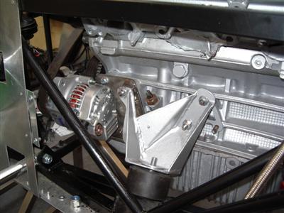
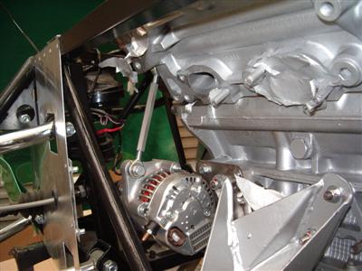
Anyway, when I had the measurements, I tack-welded the mounting bar to the plate; I deliberately put it a tiny bit short of where I thought it should be, so that I can shim the alternator forwards with washers. Whereas taking material off of the mounting to move the alternator backwards would be very tricky. This stage was crucial, to make sure that the alternator would mount squarely against the plane of the belt. Hopefully the picture should clarify things!
With it just tacked together, I carefully bolted it all in place, and was pleased to find that it all seemed to line up correctly. Then it was a relatively easy job of welding in some strenghthening ribs, adding two spacers for the engine mount studs (replacing the ally ones I'd made before with stainless, and welding them to the alternator mount), and tidying up all of the edges. I did some practice welds this time before doing it for real, and it paid off - at least some of them are quite neat, with only a few Mr. Blobby jobs. Good penetration throughout though so I'm not worried about strength.
And then I could, finally, bolt it all on, and finally, get the engine back on its mounts and torque them all back up...finally, this time (he says, hopefully). This in itself takes quite a time, particularly at the gearbox end.
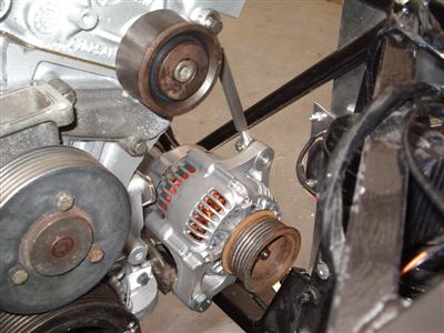
I used the old belt to make sure the alternator lined up properly front-to-back with the other pulleys. As it happened, I required just one washer to push the alternator forwards by 1mm, so I'll call that "well measured".
So that's all fine, but you'll notice that there's no way of adjusting it yet. I did a bit of web trawling, and decided rather than using the "long metal plate with a slot in it" design, (which I remember from my youth as not being terribly good - cars with squealing fan belts used to be everywhere in the winter, but you rarely hear one these days with more modern adjusters), I'd use a turnbuckle.
This is a device where you turn the centre of it to increase or decrease its length, using a left-hand threaded screw on one end, and a right-hand threaded screw on the other.
These are available from various motorsport shops (I believe used on racing go-kart suspension), unfortunately I couldn't find one in the short length I needed...so back to the lathe I go.
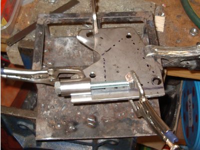
I used a length of 10mm hex bar for the body (so that it can be gripped with a spanner). An M8 hole is drilled and tapped in one end, and a left hand M8 in the other. A rod end/rose joint and lock nut into each end, and that's basically it. One end bolts to the alternator, the other to a convenient unused stud hole on the cylinder head.
The one confounding factor was that the hole on the cylinder head was only M6, and I couldn't find a rod end with a 6mm hole but an M8 thread, so I had to turn up a "top hat" reducer. Here's the finished article, minus the lock nuts which I'm still waiting for:
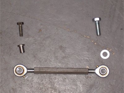 Top hat reduced is on the left hand side, between the bolt and bearing
And here, fitted:
Waterpump Outlet
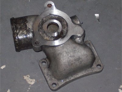
As previously mentioned, I'd sourced an old 12 valve waterpump outlet, but it needed a stud hole welding up and re-drilling. A fellow builder helped me out here, by getting a chap he knows with a TIG to weld it up for me - thanks Rallyingden! So when it came back, I needed to skim the gasket mounting face, and drill and tap a new hole.
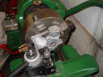
Skimming the face was another job for the lathe. I looked at bolting it down to the faceplate, but I'd have had to make up a mounting for it. So I just clamped it in the four-jaw chuck, which worked well. Because I didn't want to do the chuck up super-tight and crush it, I ran it veeeeeery slowly to avoid anything flying out of place. So each cut took about 5 mins, but that's no problem - just set it going and leave it. I took off about 0.25mm just to clean it up. Drilling and tapping was then easy enough - though I nearly cocked it up by thinking "M8 bolt - 8mm drill" and making a hole which was far too big! M8 bolt = 7mm drill (actually 6.75 but I don't have one of those). I cleaned up all of the other holes as well, and will replace the special OEM bolts (which are reknowned for rusting). Shown below being skimmed, and before drilling:
So that all fits and is ready to go - just need some new gaskets, and I'll be buying a new waterpump. I also need a screw-in plug to replace one which is missing.
Next Problem - Oil Filter
I've known about this one for a long time, but it's apparently more of a problem than I thought.
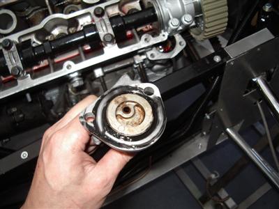
The issue is that the steering column goes through the space where the oil filter wants to be:
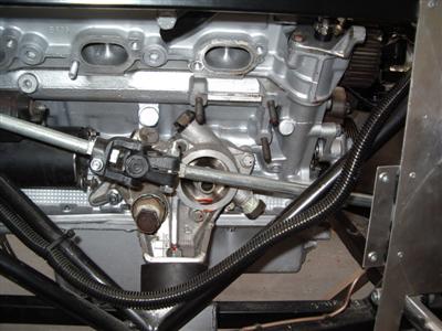
Now I had assumed that I'd get a sandwhich plate or take off, and fit a remote filter. Alas, when I came to look into it, there isn't even enough space to fit a take-off plate. Arse. I've only 35mm clearance, and the sandwhich plates I've seen have been 34mm - and they need a cover on top.
I need to do some more digging, there may be something. Otherwise I can see but two options:
- 1 - Reroute the steering column.. Pros - leaves the oil filter as it is, so no custom parts. Cons - may adversely affect steering weight or feel?
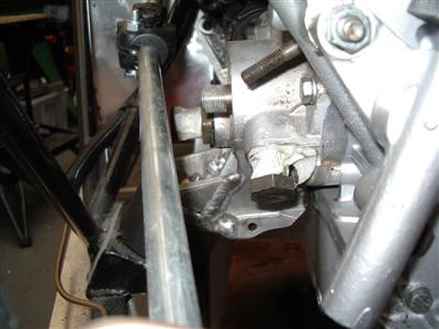
- 2 - Use the feeds for the oil cooler to fit a remote filter
Option 2 is a bit more involved, but potentially a neater solution. As you can see from the photo, there is already a pair of take-off ports, which are for the oil filter. What I could do is use these to feed a remote filter. I'd have to disable the thermostat and blank off the bypass port inside. Then I'd need a remote inline thermostat to let me feed the oil cooler. Should work, but would add an extra few hundred pounds. And it means messing with the oil system which is not something you want to get wrong. Watch this space...
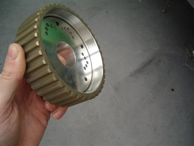
Vernier Pullies
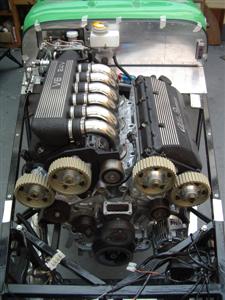
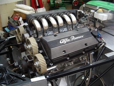
And finally, my pullies came back, machined down as requested. They now fit perfectly, and certainly don't look as if they'll be unduly affected:
All of which gives me an excuse for some gratuitous "engine porn" shots. It's looking pretty mean now: