Side Panels, Seats, Engine Parts...
17th June 2011
I've been a bit slack on the updates of late - largely because I've been trying to resurect the old man's MGB, which has been sat unused for about 7 years. It's at the other end of the country which doesn't help, but after freeing the brakes, it looks like a new battery, set of tires, and a change of fluids and filters should be all she needs to get going again. You wait decades for a project car, then two come along at once...
Flared Side Panels
Anyhow, I have managed some bits on the Rush. I finished the side panels, now I have a new rivnut tool. Four M5 bolts in the top edge and four along the bottom hold it in place - I wasn't sure about drilling yet more holes in the chassis, but the build manual has you bolting a strip of ally angle into the rail to act as an abutment for the bonnet, so I guess it's ok. I can just use the same holes for both.I've overlapped the front of the sides (got that?) over the infil panels I made ages ago. I did this because the front edge of the side panel is a nice, guilloteened straight edge, and the edge of my infil panel was hand cut and a little bit wavy. So it gives the neatest appearance. Ideally, they'd be butted together but I thought it would be hard to get a good finish.
The downside is that the two panels rattle together, so I bolted them together, using a plate inside the engine bay - bolts are arrowed:
I'll probably run a bead of sillicone sealant along the front edge when I do the final fix, just to make sure no air gets under it. Silicone peals off easily, so wont cause a problem if I need to remove the panel, unlike wurth which sticks like s"!%
Rear Undertray
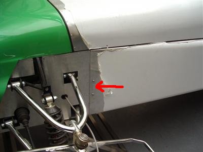
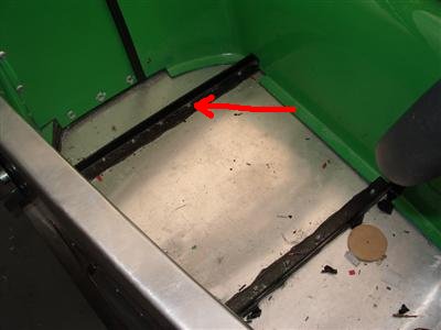
The flappy-front edge of the rear tub moulding has always bothered me, as I've probably mentioned before. Quite why they don't extend the moulding by 20mm so that it can be bolted to the fuel tank rail is beyond me: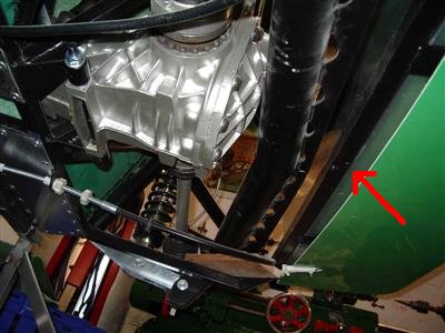
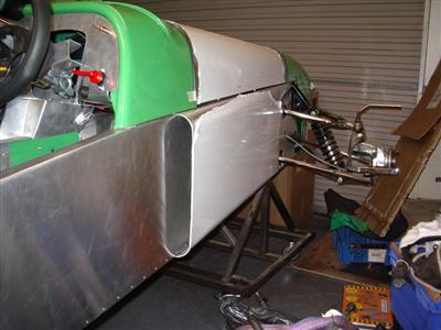
Anyway, they don't, so the front edge is completely unsupported (arrowed). So I've made up an undertay using a couple of sheets of 1.2mm ally. I had these cut to size so it was just a case of bending and rivetting. I used M5 rivnuts into the chassis rails and along the bottom of the rear tub.
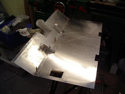
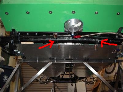
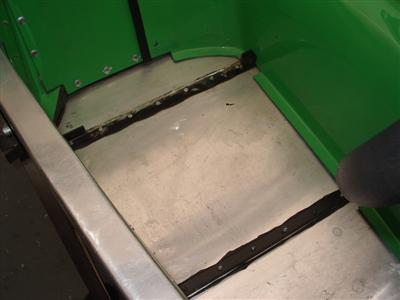
The cut-out is for the fuel filter which protrudes just below the chassis rail - this is boxed in in the finished article. There are two brackets fixed to the chassis along the front fuel tank rail, which prevent the undertray sagging in the middle (arrowed):
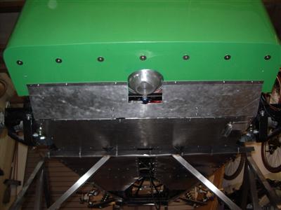
That should make everything rather more streamlined. Nice and solid too. I've not bothered trying to box in the hole around the fuel tank sump, because it's probably good that there's a way for air to get out if it gets in from the transmission tunnel.
Vernier Pullies
Some excitment the other day when my shiney new cam pullies finally arrived from Cat Cams. Almost a year to the day since I ordered them, so not exactly quick! But custom made just for me, and look like proper bits of kit:
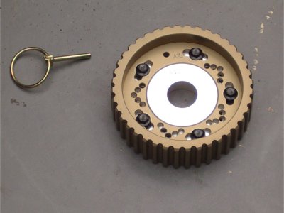
The various holes are drilled out of phase, so one pair lines up at a time. Each pair is 1 degree out, so you can adjust by exactly on degree at a time, using the pin to lock it in place whilst you do up the bolts. An added benefit is weight - these are 515g each, verses 785g for the OEM cast ones. So that's over 1Kg of rotating mass lost, which can't hurt.
Seats
Still no flywheel, which is really starting to hold me up. Although they tell me they've actually made a start on it today, so fingers crossed. Though I'm not holding my breath.
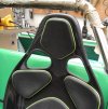
So I was casting around a bit for things to do next, and figured I might as well bolt the seats down.
This unfortunately requires a bit of grinding, as there's an angle cross-piece which fouls the seat base. By all accounts this doesn't actually weaken anything that matters, and in fact the MC chassis only has flat strips in these positions. So it was out with Mr. Angle Grinder:
I have a pair of adjustable rails which I was considering fitting, because I'm a bit paranoid about getting the seating position right. But trying them out, the extra inch of height really makes you feel a bit perched on the car, rather than in it - and leaves my head a bit too near the top of the rollbar for comfort. So I think I'll end up bolting the seat straight to the floor, and hoping I get it in the right place. So I might leave the driver's one for now, perhaps wedge it in place so that I can at least drive the thing around the block and get it as right as I can. I'll bolt the passenger one in now though because that isn't so critical.
12 July 2011
Blimey, nearly a month since my last update! In my defence, I have been on holiday, and dealing with the MGB which is now back on the road, after a few very long days getting it through the MOT. Coupled with the lack of the flywheel (still, although I'm told it should be ready this week), work on the Dax has been limited.
I have finished the passenger seat mounting though. First step was to make a cardboard template of the bolt holes in the bottom of the seat. As it happens, the two rear bolts line up nicely with the rear cross-piece, so that gives a nice strong mounting point. At the front however, the bolt holes are just through the ally floor. It seems a bit flimsy to bolt into the 1.2mm ally floor, even with a spreader plate (though I believe that this is enough for an IVA pass).
So I've placed two lengths of 2mm mild steel angle underneath the floor, bolted into the cross pieces at each end, to carry the seat. This gives a nice strong mounting for the front seat bolts, and is probably as easy as making up spreader plates. A bit heavier but not by much, and there are some things which just need to be robust.
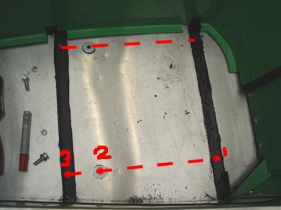
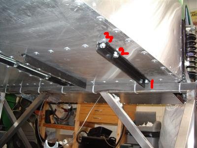 Left - dotted line shows where the rails will go underneath the floor. Bolt holes are numbered - 1: rear seat bolt; 2: front seat bolt (note washers bonded to floor to make up the height to match the cross piece); 3: rail to cross-piece bolt. Right: view from underneath.
I ran a bead of wurth along the rails to bond them to the floor, purely so they don't fall off when taking the seat bolts out - I'll have to remove them again later to put the gearbox and propshaft in.
I've spent the rest of the time doing oddy-soddy bits, but it all needs doing, so I may as well do it now.
Bonnet
There are two strips of ally angle which go along the chassis top rails and form an abutment for the bottom of the bonnet. This bolts down onto some wing piping to give a nice shut line between the bonnet and side panels. One of those easy-but-fiddly jobs to get everything lined up nicely.
It'll need final tuning when I get some bonnet catches, which I suppose I could get around to any time really. The standard method is overcentre catches, but these are having problems with IVA edge requirements. Aerocatches are popular and give a neat finish, but there's a part of me which fancies old school leather straps a la this:
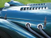
Which probably also wouldn't meet IVA edge requirements.
I'll probably get Aerocatches.
Waterpump inlet
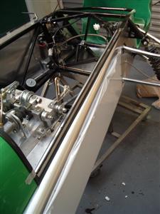
Not sure if I'd mentioned before, but the inlet for the waterpump has been bugging me for ever. It travels from the back of the engine, down a long pipe which runs in the valley between the two heads. This made sense in the engine's original transverse mounting, but unfortunately, fouls the gearbox in my case. So I needed an alternative.
I did lots of reading around, and found that some older 12v versions of the engine had an inlet into the front of the engine, which would be perfect. I managed to find one in a specialist breakers, and it fits (which is nice):
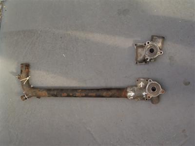
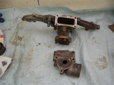 Left pic: Top - front entry 12v inlet, Bottom - 24v inlet, with long pipe which runs back between the heads. Right pic: The 12v inlet shown with the waterpump.
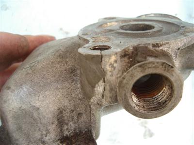
So that almost solves my problem, except that one of the bolt holes has broken off (the seller did tell me this in fairness). So I need to get it welded, and I can redrill and tap it. I'm at least happier now that I have a solution, rather than it being another big unknown.
Painting Engine Parts
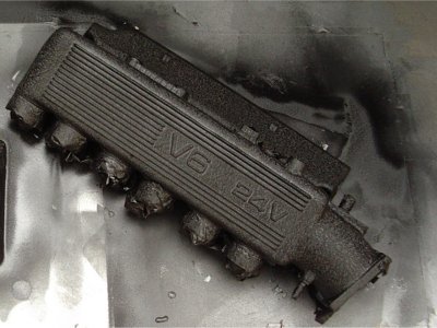
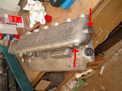
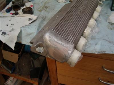
I've also been painting up the rest of the engine parts. The heads I've done in silver engine enamel to match the block. For the plenum and rocker covers, I've been planning to do them in a crackle black finish, and pick out the lettering in silver.
Because the plenum will stick out of the bonnet, I have to remove any sharp edges which would fail IVA. At the front were a couple of earthing studs and moulding lugs, so I cut them off, filed it all down, and applied a bit of body filler to give a smooth, curved finish. I also smoothed off the edges of the moulded lines and letters along the top, as I've heard of people failing on these on other plenums. Must remember to earth it from the rear somewhere!
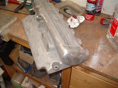
Then it was on to the paint.
The first attempt didn't go at all well, alas. I sprayed it in a shiny chrome effect paint, intending to mask off the lettering and spray the crackle paint on afterwards. Unfortunately, in the small print the paint said "not rub resistant". No shit! After 48 hours (supposed drying time 2 hours), the slightest touch still left fingerprints in it. Why make paint that can never be touched? Aaaaaaaagh!
So I had to strip it all off and start again. Bum.
This time, I started with the base coat. The crackle black takes a number of days to dry, and an hour in a low oven (90 degrees C) to cure. Then I'll file/sand off the paint from the lettering, and paint it in by hand, with silver or white enamel I think. I've done a test piece to check that it'll work, and it all looks good so far. The crackle is very hard stuff when dry.