
General Woe
26th September 2011
Before I went much further with the engine, I wanted to make sure that there was sufficient clearance between my larger valves and pistons - especially given the extra lift of the cam. The best way to test this is the "clay method". You stick a block of clay on the piston, time in the cam, and turn the engine over. You can then measure how close the piston came to the valve from the indent made in the clay.
The downside is that, if you have hydraulic tappits (as I do), they will compress giving you a false reading. To get around this, you need to make up a solid tappit of the correct height and use that instead. Now I could do this on the lathe, but I'd have to by spring compressors and dismantle the head. So I took the slightly hacky, but easier option of doing the test with no head gasket. The thinking here is that the gasket is 1.5-2mm thick, so if you have clearance without it, you should be fine with it. Not as good but would do to start with.
So, off I go to fit the various pulleys and the timing belt. And immediately hit problems - my expensive custom vernier pullies did not fit on the driver's side head.
The problem is that these two pullies are set back, (because the cylinders on that head are offset forwards compared to the other). Inside the diameter of the pulley, there is a boss which contains an oil gallery. The standard pullies are made of steel and are quite thin; the new ones are ally and 4mm thicker, and foul the boss. The pics below show the problem:
So I was pretty upset about that. Not really anyone's fault, but a pain in the arse to be sure. Hopefully, there's enough meat on the pulleys to be able to machine enough off to give the required clearance - I can't really take any off the head because of the oil gallery. So I've got the Cat Cams people looking into it now.
In the meantime, I fitted the standard pullies so that I could get on with my test.
I used the old timing belt and pullies for now, though they'll all need to be replaced for the final build. Whilst I was looking up how to tension the belt, it became apparent that I'm going to have to buy a special weighted tool which is used to set the tension. Not needed for now, but it's another hundred quid to spend...ouch.
I'd not timed in a cam before, let alone 4, so it's been a bit of a learning experience. The first thing I needed was a degree wheel for the crankshaft. Handily, several enterprising folks on the internet have provided downloadable ones - so you can just print them out, stick it on a bit of card, and you've saved yourself 30 quid or so:
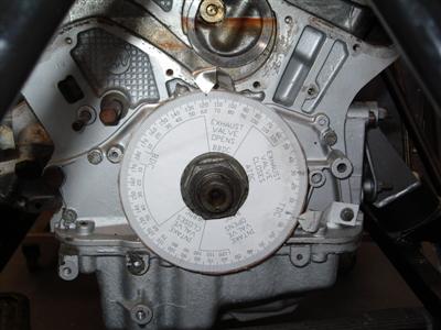
Notice the pointers (made from bits of ally and bolted onto a convenient cover bolt hole) which indicate Top Dead Centre on the front cylinder of each bank.
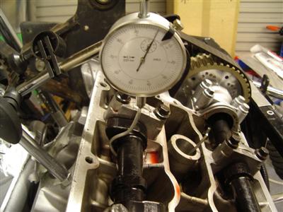
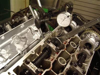
TDC was found by removing the heads and using a dial guage directly on the piston crown. When that's known, the cams can be set according to the lift at TDC figure that the manufacturers provide; again measured by dial guage. There are a lot of good guides to doing this on the 'net, so I wont go through it in detail here. For example: Burton Power's guide or this one from Alcester Racing Sevens
I did the test on both heads, just treating each bank separately. One handy tip I picked up was to make a dial guage extension using some 3mm ally wire,which can basically be screwed into the bottom of the guage, and easily bent around the camshaft. I was able to screw the guage stand into one of the inlet port bolt holes, which was conveniently the same size. Another was to remove the spark plugs and put a wire rod down each. This lets you see how each cylinder is moving - sounds trivial but is the actually really useful. (pic below)
Another, which will be obvious if you've done it before, is that the camshaft has a set of flats machined into it about half way along its length. This is so that you can turn it with a spanner! Obvious once you've seen it, but I was scratching my head for a while wondering how to do it.
So that all took a couple of evenings, by the time I'd read about it, measured everything, done it wrong, redone it, etc. And the good news was that everything moves nice and freely. I had a good peek into the ports and plug holes with torches and mirrors as well, and I'm pretty happy that there's plenty clearance in there.
Unfortunately, fresh on the heels of the good news, came the bad. Firstly, I suffered from the dreaded slipping spanner and put an almighty ding into one of my brake pipes, so I'll have to replace that. And worse, whilst I was mucking around with pullies, I noticed that the engine was much closer to the chassis on the passenger side than on the drivers side. Much, much closer, as in, about 5mm away. That certainly wasn't as I remembered it, so I went back over my photos from when it was fitted before. And indeed, in the previous pictures it was equally spaced, with about 20mm clearance on both sides.
What had changed? Had I not bolted everything up properly before, and now I had it was pulled out of line? Perhaps my gearbox mount was slightly off? To find out, I'd have to unbolt everything, hoist the engine up a couple of inches, and wiggle it around to see where the problem was. Arse! Yet another problem - it seemed that every time I had looked at the car of late, I found something seriously wrong. For the first time since I started, I was actually annoyed with the thing.
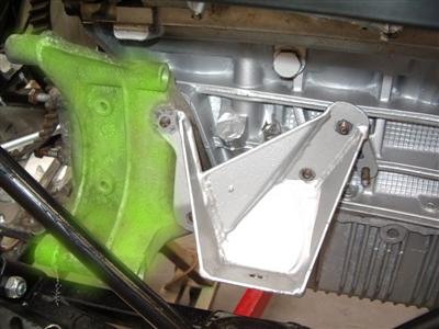
Still, getting annoyed wasn't going to fix anything, so at the weekend I set about unbolting and lifting the engine, again. Doing this took an few hours - there's quite a lot to take off now to be able to lift the engine. And the gearbox mount in particular is a real pain, as there is very little space in the transmission tunnel. But, when it was lifted up and I could move it around some, and by comparing with the old photos, I was able to find the problem. The mount had been fabricated to sit on the alternator mount; I'd discarded this because it is huge and heavy. This meant that the mount was closer in to the side of the engine, which had the effect of moving the engine closer to the chassis on that side. I've highlighted the old mount in green below - you can see how it spaces the engine mount away from the block:
At this point I was focussed on getting the thing to fit properly, so I machined up a couple of spacers to make up for the missing alternator mount, and put it all back together. Lo and behold, the engine was now properly aligned. Happy days! So I commenced bolting it all back in place. I was nearly finished when it occurred to me that I did actually need an alternator; even if not using the stock mount, I will very probably need to use the same mounting studs. And to do that, I'll need to lift the engine, again...sigh. So I think my next job needs to be to buy an alternator and buy/fabricate a mount.