Column Switches
17 March 2011
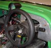
OK, so I had a list of things to do before I can put the engine back in, but as I was refitting the tunnel, steering column and a bit of the dash in order to check the clearance of something, I got sidetracked into looking at the column stalks. As I'd mentioned, the sierra ones are a bit far away from the steering wheel, so I needed to modify them somewhat.
Then, I was browsing the web, and happened across this page on a Tiger build diary. The chap replaced the Sierra switchgear with more modern ones from a Peugeot 106 (which also seem to be shared by the 206 and Citroen Saxo). And it seemed like a jolly good idea - the sierra stalks are rather dated looking, and it would be nice to have modern twist-on headlights.
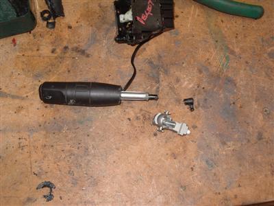
So I thought I'd give it a go - onto ebay, and bought myself a pair of switches for about 15 quid. So far, so good.
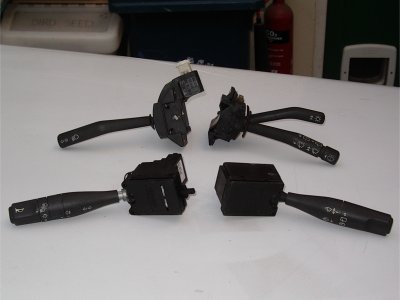
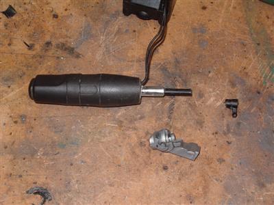
As you can see, the switch base is much wider on the new ones, but the stalks themselves do look a lot better I think.
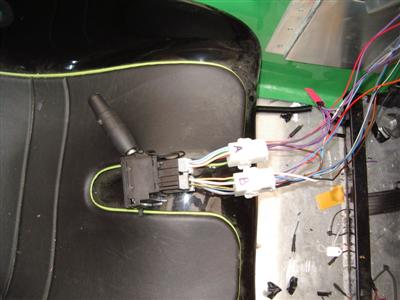
Next step is to make a bracket to mount them to the column, to see how they sit. I was going to template it in card, but in the end just did it straight in the metal. It worked first time, too - I must be getting better! 1.5mm ally sheet is used. The four original sierra screw holes are used, in addition there's a convenient hole in the top of the column support which I tapped to M5 to make a central mounting point. It looks a bit unfinished in the pic, that's because it was at that stage!
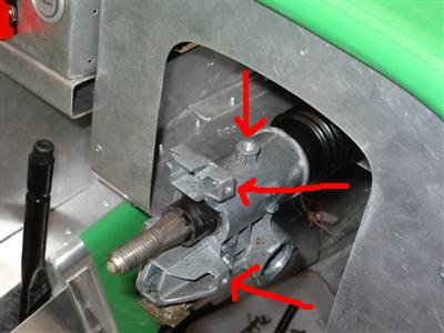
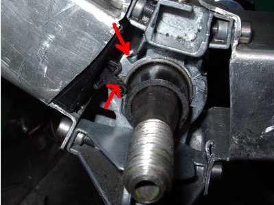
So with that done, I could fit the stalks and see how it looked. First, though, there were a couple of problems with clearances to sort out. A small section of the column support needed filing back (top arrow) to allow the self-cancelling mechanism (bottom arrow) to move without jamming; and the bottom edge of the self cancelling mechanism needed 1mm filing off it to prevent it catching on the edge of the bearing race. Simple stuff, but vital - it's obviously essential to make sure that there's no way it could jam the steering. So I spent a fair bit of time playing with this until I was happy.
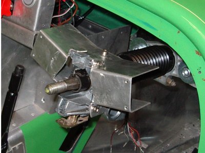
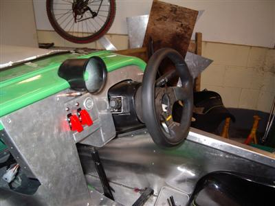
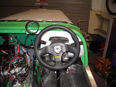
Then I fitted it all, and the positioning seemed good. The downside of it is that the larger bases will stick out of the column shroud a little. I looked into using a peugeot column shroud, but they are god-awful looking devices. Since I'd already decided I needed to do some filling and covering of the shroud I had, I bit the bullet and chopped some bigger holes in it. Put it all together, and this was the result:
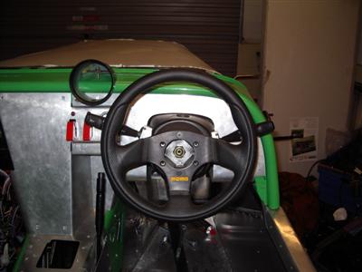
I'm happy with the protrusion through the shroud - when it's all finished and the ally painted black, I think it will look fine. The bit I didn't like so much is how far the switches stick out the sides - they are much wider than my weeny steering wheel. That said, they are in a much better position than the sierra ones, so that's all good.
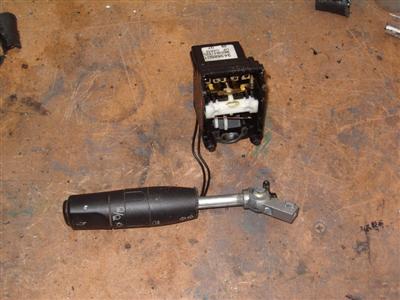
Still, I couldn't resist seeing if I could shorten the stalks a bit to make them perfect. Since they'd only cost a few quid each, I figured I could risk taking a saw to them.
I started on the simple right hand one, which has fewer functions on it. It has a twisty end for a rear wash/wipe function, which obviously I don't need, so I didn't bother retaining that. It basically consists of an inner plastic stalk, with an outer shroud, so it was easy to saw through, cut a chunk off the shroud, and slide it further down the stalk. All glued back together with epoxy.
The other one was more complex; It has twist switches for fogs and headlights, as well as indicators and main beams. In the end I had to sacrifice the first one getting it apart to work out what I needed to do, so I ended up buying two.
Basically, there's a hollow metal core, which has a plastic actuator rod running through it, which does the horn push and twist on headlight switch - the actual switch gear is in the base. The whole lot is glued together and can't be disassembled without destroying it.
So I first cut through the plastic shroud with a hacksaw, and cut away the lower part - taking great care not to cut the two wires which run down from the fog light switch!
Then, I cut away the metal core at the point where it forms the balljoint, taking care not to cut through the plastic rod inside. I cut the end of the rod the other side of the joint, and saved the little plastic actuator.
From there, I drilled out the balljoint so that I could push the metal core into it. Then trimmed the metal core down so that it was all flush. Finally, shortened the plastic rod so that it protruded by the right amount, and drilled a hole through the acutator, so that it could slide back over the rod. All glued together with epoxy and Uncle Bob is in the house. I forgot to take a pic of the finished parts, unfortunately.
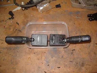
All of this effort left me with a pair of "stubby" stalks, 30mm shorter than before. It's all put together a bit wonky in the pick below, but it shows the width of them. Much better than before, still a little further away than I'd like but not by much - and I've got to consider driving with gloves on so a bit more clearance is probably a good thing.
I'll give the logos a bit of a spruce up with some white paint when my hand is feeling steady!
The final thing is wiring them up. I got some connectors with them, but I needed to reverse engineer them to work out which wire did what. It took about an hour sat in the front room with a continuity tester, methodically checking each possible pair of wires for each switch position, to work it out, so not too bad. Well, it beats watching "Glee".
Left Hand Stalk Connectors
Note - the pin numbers are just what I've used on my diagrams, they wont match anything official, and are shown looking from the back of the switch.
| 1 | 2 | 3 | 4 | |
| 5 | 6 | 7 | 8 | 9 |
| 10 | 11 | |
| 12 | 13 | 14 |
| Pin | Function |
|---|---|
| 1 | Main Beam Flash |
| 2 | Right hand indicator |
| 3 | Left hand indicator |
| 4 | Common 12v feed for indicators (pins 2 and 3) |
| 5 | +12v feed for Headlights and Fog lights (pins 9 and 12) |
| 6 | Main beam on/off (on when stalk is fully pulled back) |
| 7 | Common 12v Feed for Main Beams (pins 6 and 1) |
| 9 | Fog lights |
| 10 | Horn, along with pin 11 (either could be +12v or earth) |
| 11 | Horn |
| 12 | Dipped Headlights |
| 13 | Sidelights, along with pin 14 (either could be +12v or earth) |
| 14 | Sidelights |
Right Hand Stalk Connectors
Since I've disabled the rear wash/wipe function, it's not in the list.
| 1 | 2 | 3 | 4 | 5 | 6 |
| 7 | 8 | 9 | 10 |
| Pin | Function |
|---|---|
| 1 | Fast wipe |
| 2 | Slow Wipe |
| 4 | Common 12v feed |
| 5 | ON when Wash (pull back), OFF normally |
| 6 | Intermittent wipe |
| 8 | OFF when Wash (pull back), ON normally - park? |
31 March 2011
Lots of Wiring
Spring is here, and it was the first NW Dax owner's club meet last weekend. Only one brave soul in a Rush, but it was good to catch up with everyone. Still pretty chilly some nights in the garage as well, but getting warmer, which is always pleasant.
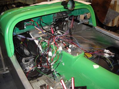
Not so much done on the car this week, as gardening chores reared their heads, but I've got a bit done on the wiring side of things.
What took the most time was wiring a new set of connectors to the short lengths of wire I had comming off the column switches, and adapting the main loom to suit. I've just used some generic 3x4 connector blocks - could have used one smaller one, if I wanted to be fussy about things, but I used what I had.
The biggest change was for the main beam on/off switch. In the sierra, it's a standard push on, pull off switch; the peugeot however uses a pull on, pull again for off momentary switch. I prefer the sierra way, but my road car is the same as the peugeot, so I'm not overly bothered. Anyway, in order to make the momentary switch work, you need a latching relay. This is a type of relay which, when activated, switches to either on or off, and stays in that state using a mechanical latch.
As I found out a couple of days later (after I'd bought and installed the latching relay, naturally), this isn't the case. The column switch itself deals with latching on and off, but only when the headlight switch is turned on - this is why I hadn't noticed it when I was testing everything. Since I'd already wired it all up to use a relay, I simply replaced the latching one with a normal one, rather than strip out and replace all the wiring again.
Of course, there's still the main beam flash as well, which doesn't go through the relay, so there's a few extra wires to put in. One thing I have found is that I always need to add a new wire just after I've neatly taped everything up and covered it with heatshrink!
Testing
Finally, last night, I got to the point where I'd connected everything up to the internal loom, so it was time to run some power through it and see if it all worked!
Before doing this, I went round and taped over any exposed wire ends to prevent shorts. I also connected a fuse between the battery +ve terminal and the loom, as advised in the manual to protect against shorts. I just used an ordinary household 3A fuse, some crocodile clips and some spare bits of cable. I guess the fuse could bear to be rather smaller at this stage since I'm not actually putting any load on anything.
All that done, I gingerly connected the battery up...and nothing sparked, shorted, or caught fire. First hurdle passed! Then it was a case of methodically testing each switch, and checking that I got +12v out of the appropriate wires using the multimeter. It's fairly time consuming to check each combination of switches, (for example, fuel pump is on when fuel switch is on AND ignition is on AND the ECU says so, so there are 8 combinations to test to make sure there are no loopholes) but not difficult. In the case of ECU controlled switches, I'm having to simulate them since I don't have an ECU yet.
I found one missing earth lead (I just hadn't connected it up), but everything else so far has worked first time. It feels like the first bit of life has been breathed into the car now, as if it's starting to become a working machine at last. Still a long way to go but it's another milestone...and it means I can finally start fastening all of the wires into place, rather than having them spilling everywhere.
Clutch/Flywheel News
Forgot to mention - bit of a 'mare with the whole clutch thing. It became apparent that the original flywheel was out of balance (deliberately). After much research, it seems that they have the flywheel weighted on one side, and the crank pully weighted by the same amount on the opposite side. So as a whole, it's balanced. The offset weights at each end apparently smooth out some end-to-end crankshaft vibrations, from what I've read.
Anyway, the upshot is that I'll need to get the whole lot (crank, flywheel, pulley, rods and pistons) balanced in the block. Which means a whole load of expense I wasn't expecting, plus a day off work to transport the whole lot to the balancers...and to top it all, the engine will have to come to pieces again.
The flywheel is being made as we speak, so I'll soon be pulling apart my lovingly-assembled short engine and loading it into a transit, again. Sigh.