Again...
Scuttle, More Wiring
6th April 2011
Well, it's going to be a few more weeks until my flywheel etc is ready, so I've been forging ahead with the wiring end of things.
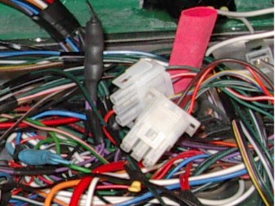
The Dax loom comes as three separate looms - engine bay, internal, and rear. They connect using mutliconnector blocks, which are pre-fitted to the internal loom (the jumble of wires in the scuttle), but not to the other two - this is so you can feed the wires through holes in the bodywork etc. They've been in place for some time now, and I've not had to remove them recently, so I figured I was safe to put the connectors on. Once on, it'll be a real pain if the cables ever need to come out again.
All of the terminal ends are fitted, so it's "just" a case of pushing them into the connector blocks in the right positions - basically matching the cable colours up. Easy enough, but fairly time consuming - you can get terminals out of the blocks once pushed in, but again it's a right PITA. So it's worth taking the time to get it right first go!
The more bits which get connected, the more sense the big jumble of spaggetti starts to make, so I've also started to tie bits of the internal loom in place - using cable ties and self-adhesive bases. So it's gradually getting a bit tidier.
Connectors, Tools etc
It's not worth going into the details of every last wire I've connected, but what might be useful to some readers is a bit of information about the gear to use. I've ended up buying various bits, some of which were useful, some of which were wrong, simply because you often can't tell until you've got it in front of you.
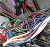
I started off using pre-insulated connectors, which come in Red, Blue and Yellow sizes. These are ok, but a bit clunky looking and no good for connecting relays etc. So you're better off getting the uninsulated types - these normally fit into connector housings, but where required can be insulated with heat shrink. No-one really seems to sell selection packs of uninsulated connectors, and there are many types, so it's hard to know what you need to start off with. Actually though, it's very simple.
What you need are 6.3mm Male and Female blade connectors, WITH TAGS. (the tags mean that they snap into plastic holders and relay bases):
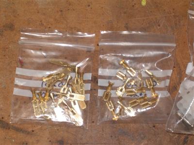
You might need the odd one or two in a different size, but these are used for virtually everything - connecting to sensors, relays, switches etc. They come in a couple of sizes for different sizes of wire.
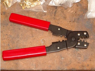
You'll need a crimping tool to crimp them on, these are easy enough to find.
Then you'll want some connector housings for the blade connectors - you can have a single housing, or ones which group several connectors together in a block. The blade connectors just snap into these:
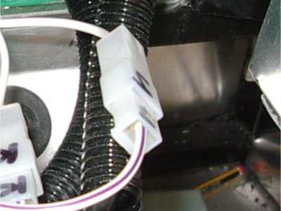
Finally, if you want to group more than a few wires together into a block connector, the "Mate-n-Lock" connector blocks are an alternative to the blade ones, and take up less room. These are more for joining wires to other wires, the blades seem to be more for joining wires to components. They come complete with terminals, and the same crimping tool is used.
The above is what I've used for virtually everything so far, so it's a good starting set up. You'll need some heat shrink and a heat gun as well really. Once you get going, it's obvious when you need a different size for an odd switch or wire - getting going is the hard bit!
Inertia Switch
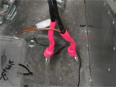
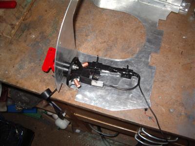
I also wired in the inertia switch I'd bought previously. I decided to mount it in the front of the scuttle, with the switch in the engine bay. It's out the way but easy enough to get to should it be needed (hopefully never), and also well placed to splice into the fuel pump wire connection between the internal and rear looms.
It's a bit of a funny shape, so I had to cut an upside down "T" in the front of the scuttle to get it in. I made a small ally plate up to slide in behind and cover the gap, which looks quite neat:

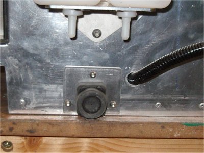
Rather than drill more holes in the chassis to mount it, I glued it to the scuttle with epoxy. I should mention that I played around with this one, and it has to be mounted on a horizontal surface in order to work - I considered mounting it vertically, but in that position it's always on, so would serve no purpose. Worth watching out for.
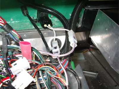
Wiring up was then fairly easy - it goes between the internal and rear fuel line cables. I made up two trailing leads from the switch itself, connected with blade connectors, to fit the ones already on the loom (the white and purple wires). There is a third connector on the switch which is live when the switch is off - so I could use this to drive a warning light to indicate if the switch has been tripped. Might do, if I run out of other things to do.
Scuttle Position
Ages ago, I'd glued some wing piping down for the scuttle to sit on. Since then, my carefully measured bonnet shut line had developed a rather large gap. Part of it was because the wing piping under the front of the scuttle meant that it was slightly tilting backwards - when it's finally mounted, there will be piping under the rear edge which will bring it flat again. However, that wasn't all of it. I've been looking at it on and off for weeks, and never really got to the bottom of it; I can only assume that something moved when it was drying. Anyway, I wasn't happy so I had to do it again.
Peeling the wing piping off wasn't too bad, but removing the old wurth from underneath was. The heat gun and a gasket scraper helped a lot here. To cut a long story short, I had to adjust the bonnet hooks to move the bonnet backwards by about 5mm, and with the scuttle as far forwards as I can get it, and the rear of it raised as it will eventually be, I finally got a nice neat shut line. I glued down the wing piping again, and hopefully nothing will move this time! It seemd to be fine the next morning at least.
Odd bits, and Next...
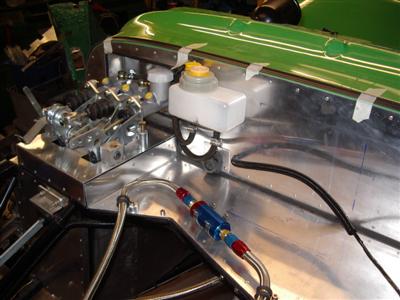
A few other odd jobs done, like making up and welding on the two extra earth studs for the battery and starter. I've decided to fit a battery master switch as an extra safety device (plus a bit of extra security), since there are a lot of wires which are live even with the ignition off - there's plenty of extra length in the main battery cable so it's going to be easy to do. Then I've got a couple of small side pieces I need to make up for the dashboard, tidy up the wiring a bit more, and various other exciting bits.
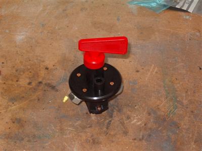
Battery Master Switch
19 April 2011
As planned, I bought a battery switch. There are very cheap ones which are just an on/off switch, the better ones however come with a second pair of contacts and a big 3 Ohm resistor. This pair of contacts is used to give a route from the loom to earth, through the resistor, when the switch is turned off. The reason for this (as I understand it) is that, if you completely isolate the battery with the engine running, the alternator will continue to turn for a second or so, generating power, which has no-where to go, and which can end up causing damage. So instead of just isolating everything dead, the switch dumps this excess energy to earth, via the big resistor which just converts it to heat. I think :)
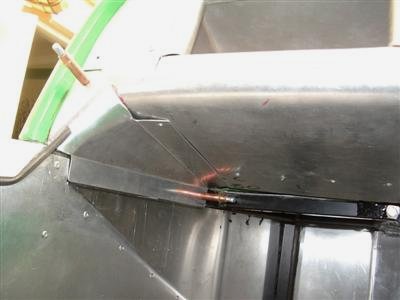
Easy enough to fit anyway, into the dash on the right hand side below the steering wheel. I cut the main battery cable (actually 3 large cables taped together) and soldered on a couple of large M10 ring connectors. The resistor has to be soldered on, I then heat shrunk it, and wrapped the whole lot in loom tape, before attaching it to the inside of the dash with cable ties. It's the long black thing in the pic
As usual, I forgot to take a pic of it all finished!
Dashboard Side Panels
Finally, I got around to making some side panels to finish off the dash. For some reason I'd never quite got round to doing them. Here's one:
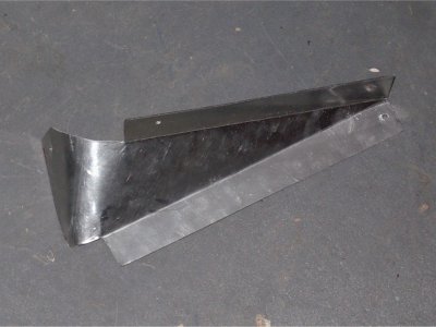
Simple looking thing aint it? But it hides sooooo much effort. It's actually quite a complex shape, the curve is a cone shape, at a funny angle, and the two bends are converging - all of which makes it incredibly hard to fit. This was actually the 6th attempt; by my count I spent around 10 hours to get this far. Having done it once, the other side "only" took 2 hours. Still, finishes it off nicely, and supports the outside edge of the main dashboard.