Planning...
03 November 2009
Soooooooooo....much head scratching has passed, and I think I have a plan. I'm going to fabricate a new gearbox mount to make the box sit lower (Pete F ended up doing the same), which I've roughly designed and ordered the bits for. That in itself has involved many hours browsing the internet looking for ideas, and then suppliers; as usual, eBay has come to the rescue. All a bit of an educated guess, since I have no experience of designing and building anti-vibration mountings for gearboxes, so I've no idea how well it'll turn out. But it can't stay as it is, that's for damn sure.
As I've found a number of times, knowing the correct name for something is the key to finding it, and finding that name can take time. So, as above, "anti-vibration mount" is the keyword to use when searching for metal/rubber mountings for engines and the like. Just thought I'd mention it...
Honda S2000 Gearstick
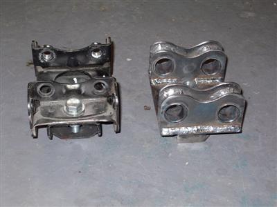
In a desparate bid to do something in the garage, as opposed to on the pc, I got around to looking at the gearstick. This has an unusually large shaft, which (topically) contains a rubber anti-vibration mount. This was (a) scratched and dented and (b) a bit too wide and high. So after a chat with a few s2000 dax builders, and yet more internet reading, I decided to take it off. I'm never a fan of butchery, but in this case there is no other way to get it off. So out with the angle grinder it was. In case anyone is planning this, these pics may help:
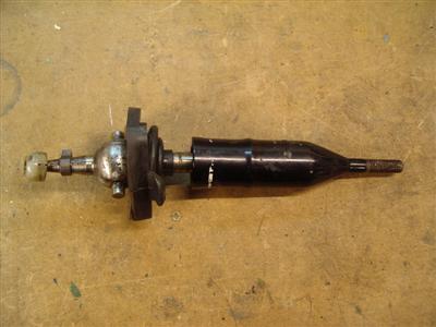
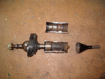 Left - stock gearstick, with large rubber-mounted shaft. Right - cutting off the shaft reveals a rubber mount at each end
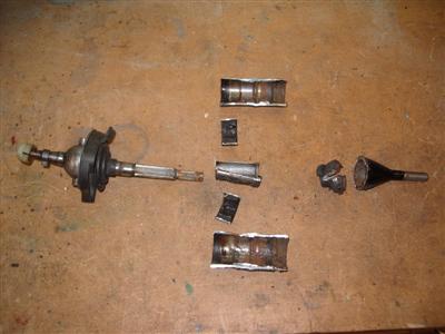
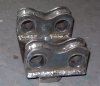
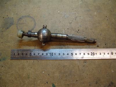 Left - each mount is attached to a thin tube which is pressed onto the inner splined shaft. Right - the bare gear lever. Note that it's bent; apparently there is a version bent to the right for RHD cars, and to the left for LHD cars. The grove in the shaft most definately isn't where I went too deep with the angle grinder. No siree.
When I can see where the gearbox is going to fit, I will probably make up a new shaft in shiny stainless so that it all looks nice. Whether this will be a cut and weld on job, or perhaps just a sleve over the existing shaft, I don't yet know. It's all complicated by the bend in the shaft, which means that I can't just stick it in the lathe. Ah well. And I have to say, the balljoint seems to be very pock-marked considering this box was only supposed to have 17000 miles on it.
Next Steps
So then I found myself with not a lot to do. There are things which I could, but don't want to yet - I could fit the front suspension, for example, but that will cut down on working room around the car, so I'd rather leave it for a bit. So instead I considered my plan of attack:
- Gearbox mount: Definately the next step. I need to do this so that I can fit the tunnel, so that I can do the footwell panels.
- Footwell panels / transmission tunnel: Waiting for the ally sheet, but that will be here before I've sorted out the gearbox, I'm sure.
- Side panels: I need to leave these until I've fitted the scuttle, so that I can make sure they match up.
- Remove engine and rebuild: The biggy. Before I do, I need to decide on whether I'm supercharging or NA tuning. I'm becomming more and more convinced that the supercharger isn't going to fit without some heavy compromises. NA tuning has always been my preferred route, but will cost more. Either way, I need to know before I rebuild.
- Clutch: I'll need to modify the flywheel, so that has to wait until the engine's in pieces.
- Propshaft: Any time after the gearbox mount is finalised
- Fuel system: Can do at any time really, but I need to know the engine's requirements, which means I need to know what I'm doing to the engine first.
- Electrics: Still waiting for my wiring loom...but I guess I'll do this after the engine is fitted anyway.
- Wheels and Brakes: As with the front suspension, I want to leave these a bit because they take up a lot of room.
- Other bodywork, dashboard etc: Need to get the suspension and engine in first.
That's probably enough to think about for now.
Gearbox Mount
17th November 2009
A brief update. I designed the new mount with a few sketches, and ordered some more 3mm steel plate to make it out of. After a great deal of searching for some suitable rubber mountings, and finding little (everything is just the wrong size or vaaaaastly expensive, but mostly just the wrong size) I've decided to use the same bushes which Dax use to mount the diff. This largely because I have some (for the front suspension) and because I'll be able to buy some more from Dax. Plus, if they are ok to mount the diff with, one would assume that they'll be ok for the gearbox.
It's not quite finished yet, because I ran out of steel plate, but some more should be here soon. It consists of a box which bolts to the chassis mount, with a plate on top, to which is welded two side plates. These hold horizontal tubes into which I'll press the rubber bushes, and run two M12 bolts through the gearbox mounting holes. I had to bore out the tubes on the lathe to get the right clearance, as I couldn't find any tubing with the correct inside diameter. The pictures below should give an idea; only one side plate is on at the moment:
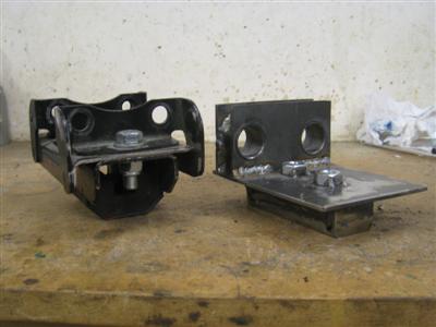
You can see that this has lowered the mounting holes a fair amount, about 23mm, which will make all the difference. Once the other side is done, I'll be tidying up the edges and giving it a few coats of paint. But it looks quite promising at the moment.
24th November 2009
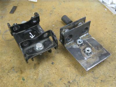
Mount is now finished, and currently air-drying under a couple of coats of PQR-15. Here's a couple of pics before painting:
I need to cut the bushings down to size yet, but that's it basically done.
In the meantime, I've been having a bash at getting the transmission tunnel to fit. Unfortunately, it doesn't seem to want to. Having cut a hole for the gearstick, I found that the front of the tunnel sits on the chassis rail in such a way that the bottom of the tunnel doesn't reach the floor. Also, there is a large gap where the tunnel meets the rear bulkhead:
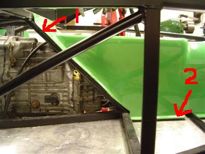
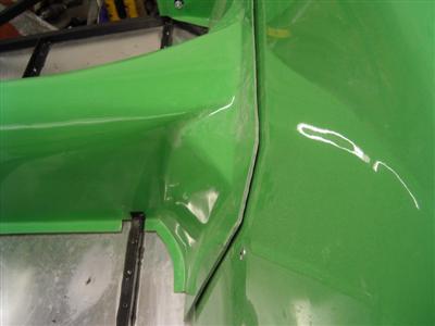 Left - tunnel resting on chassis rail (1), leaves a gap between the base and the floor (2). Right - gap at the rear bulkhead
Looking through a couple of build diaries, this is apparently not uncommon; quite normal in fact. Not that that makes it any better. When using the Dax carpet set, it is all hidden, but I am not planning on carpetting over the tunnel. So the trick will be making it fit without too much friggery. I'll be taking it slowly...
3rd December 2009
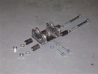
After the mount had dried, I trimmed about 5mm off each bush with a hacksaw, and pressed them in as for the diff mounts. Then it was the moment of truth. I'm happy to report that it all bolted into place pretty easilly; one of the bushing holes is about a mm out, but there's enough movement in the bushing to mean that it doesn't matter. Looks pretty good I think:
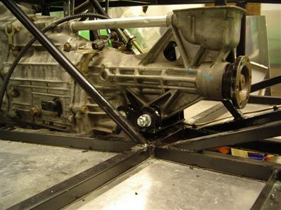
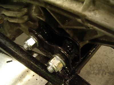
So it works, in that it holds the box; of course, I wont know if the bushings are compliant enough, or if it'll be like riding on a washing machine until the first drive.
As well as the mount, I've been working on the tunnel. After much consideration, I've elected to chop the flange from the front of the moulding (where it was fouling on the chassis rails). This let it drop into place pretty well, but leaves a big gap at the front which I will need to replace in ally - should have a picture here but I seem not to have taken one. After doing this, I found that Pete F did exactly the same with his Honda-engined Rush, so I felt a bit better. I'm very keen to make sure that the tunnel is easily removable, for when the engine (inevitably) has to come out in future. I've heard several stories of woe where people have rivited and bonded the tunnel in place, then had to cut it into bits in order to get it off later.
With the gearbox in its final position, and the tunnel likewise, I could finally see about the footwell panels. The passenger one will be fairly simple, but the driver's side is a much more complex shape. I've spent a couple of nights making up cardboard templates for each, and I think I can do each in a single piece, with perhaps a touch of welding at the corner seams. With that done, tonight I've removed the engine (again), as I'll need to work from the inside of the transmission tunnel.