
Panels and Brake Lines
09 October 2009
After the rather long designing and building session that was the handbrake, it's back to following the build manual, hopefully moving a bit more quickly.
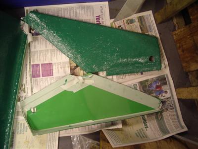
First off, I painted the unfinished backs of my GRP rear quater panels and bulkhead with dark green exterior gloss paint. A number of people have advised doing this, for a couple of reasons. It offers some protection for the GRP, particularly on parts such as wheel arches. It also apparently makes the colour of the gelcoat more vibrant in bright light; and it seals the grp so you don't get odd bits of fibre in your hands / clothes.
Whilst that was drying, I moved onto the main rear brake line which runs down the transmission tunnel. In order to make sure that there was clearance, I had to fit the tunnel itself, so I thought I may as well go about making the cut-out for the handbrake.
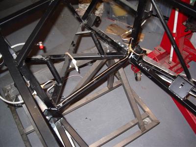
Obviously, I was a bit nervous about taking the angle grinder (stone or metal disks seem to work equally well) to the shiney GRP, so I measured, remeasured, test fitted, remeasured, etc etc. I actually put the handbrake in a central position first, and cut a hole just small enough for it to go through. Then progressively widened the hole to allow it full motion, which took a number of trial fits and cuts, but left me with a perfectly-fitting hole:
It'll need some ally panelling around it later of course, and I'll have to cut another hole for the gearstick. So for now I've left it as the smallest possible hole, just to get it to fit. The tunnel still isn't quite fitting at the front, I think due to the modified chassis, so I think it'll take quite a bit of work to get it properly seated.
With that done, I was able to fit the brake line. This was rather fiddly at the rear, because of my upside-down rear union, so again it took me a couple of attempts to get the pipe so that I was happy with it.
I figured I'd move on to making up the front lines now, before I loose the knack of pipe bending again. But when I looked, I couldn't see where the flexible hoses where supposed to attach. There are brackets on the chassis at the rear, but none on the front, which didn't seem right.
So I asked on the Dax Forum, and it turns out that on the car chassis, they are supposed to connect to the GRP side panels, whereas the bike chassis (with flared ally panels) has brackets welded to the chassis.
Unfortunatley, mine is a car chassis with flared ally panels...so no bracket and no GRP side panels. So I will have to make up a couple of brackets and weld them on myself.
20 October 2009
Having trouble finding time to update this diary at the moment, the curse of the decorating / diy is still upon me.
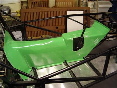
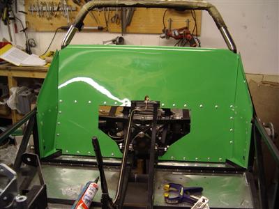
For some reason I can't remember, I elected to fit the rear bulkead and quater panels next, rather than sorting out the front brake lines. Probably to clear a bit of space in the garage - bodywork is difficult to store. Anyway, the quater panels went on without too much difficulty. Held on with a few big head 5mm rivets and wurth.
The bulkhead was a different story. The top curved bit, which fits over the horizontal chassis tube, didn't - fit that is. It had a number of thick lumps in it which meant that it wouldn't sit on the tube properly. I had to spend a couple of hours sanding (by hand, because it's such an awkward shape) and trial fitting to get it to fit. Even then, it's very tight - the shape of the curve is such that it doesn't easily settle down onto the tube. But that must be how it's meant to be, because it fits everywhere else properly.
That done, it was just a case of drilling all the holes. Use of clekos essential here to make sure nothing moves between drillings, I think you'd have a job doing it well with clamps.
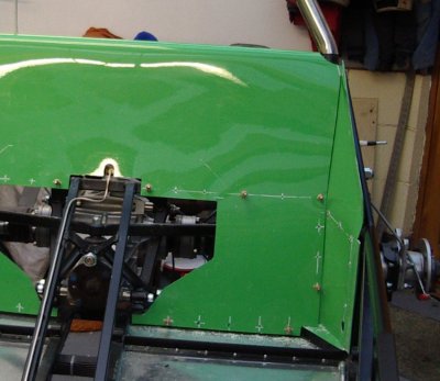
I've gone with holes all around the edges - seemed the most sensible way. The GRP stands off the chassis in a few places (down the outside edges) and I wasn't sure if it was supposed to be pulled down with the rivets or not. Eventually I decided that they it should be, which fortunately turned out to be the case. I've been using a liquid chalk pen to mark out the grp, hence all the white lines.
So then, just the usual sanding off of the powder coat, beading with wurth, and riveting on. Followed by wiping wurth off of hands, face, bodywork, tools, etc etc. Definately keep some cellulose thinners handy when using this stuff, 'tis evil.
I made sure to fill around all of the joins between the panels, and between the panels and the chassis, to make sure there's no ingress of road filth into the passenger cell. The top section of the bulkhead (where it isn't rivetted) stands off of the chassis by about 5-10mm. It's not going anywhere, but looked as if it might vibrate or rattle a little. So just in case, I used wurth to make a couple of "pads", about an inch or so long, between the chassis and back of the bulkhead. That should stop any vibration.
That done, it's back to the front brake lines. I've made up the two brackets to hold the flexible hoses, now I just have to weld them on.
25 October 2009
The brackets were welded on without incident, and after a coat of paint, I was able to finish off the brake lines. As with all the others, it took a bit of time to get them neat.
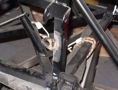
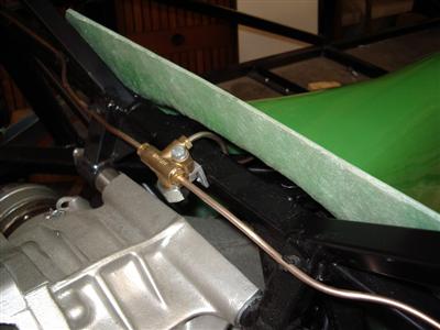
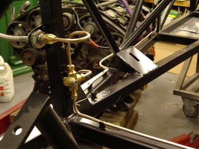 Left: Bracket welded on, before painting. Right: With the flexible line and rigid lines attached, also showing the position of the 3-way union.
Since I'm not using the pre-made lines from the kit, I had more flexibility as to where I fitted the 3-way union. I've put it on one of the upright chassis members, rather than on the bottom rail as it shows in the manual, to keep it all out of the way when I'm furtling around in the engine bay.
So apart from the final connections to the master cylinders (which I won't be doing for a while yet), that's the brakelines done. The next job to look at is making up some ally panels for the insides of the passenger compartment and the sides of the footwells.
27 October 2009
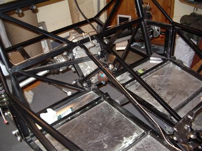
In preparation for measuring up for the panels, I needed to refit the engine and box. I now had the gearbox mount which I didn't have the first time, so I could get a true picture of where it would all sit.
First problem I found was that the mount was too thick; I couldn't get the end of the gearbox onto its mount, and the engine onto its mounts, without the top of the gearbox fouling the chassis. It's close, about 10mm, but simply wouldn't go. So I had to remove the gearbox mount, drop the engine onto its mounts, then hoist up the end of the gearbox and fit the mount underneath it.
Not so bad once I'd worked it out, but it showed another problem. The gearbox mount is simply too thick; the end of the gearbox is pointing upwards at quite an extreme angle compared to the differential; and secondly, the top of the gearbox is above the transmission tunnel, which isn't much cop. The pic below shows the alignment issue:
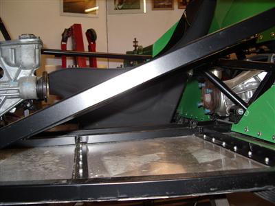
I'm surprised that Dax didn't pick this up and drop the gearbox mount by a few cm to be honest. Anyway, an hour's searching on the DROC forum however showed me that I'm not alone; Pete Findlay's S2000 rush build has run into the same problem, so I'm hoping that he's already solved it :)
On a more positive note, I fitted a couple of long bolts to hold the diff in. The theory goes that with a short bolt on each side, one may come loose, leading to a twisting force on the diff casing, which can eventually split. Ford apparently originally used single long bolts through both sides, which prevents this happening. Someone on the DROC forum found some 12.9 grade bolts of the correct length at a good price, so I figured I'd fit a pair to be on the safe side. Unfortunately, they're not zinc'd (apparently it can mess up the heat treatment on very long bolts), so I've given them a coat of chassis paint and lots of grease to protect them.