Where shall I stick it?
Handbrake
13 August 2009
So the next item on the list was to sort out the handbrake. Cue lots of sitting in the car faffing around trying to workout where to put it. To help my thought processes, I fitted the rear handbrake cable, then the front, in the standard "under the steering wheel" position to see how it all looked. I found that even in the standard position, the front cable would be fouling the gearbox; there have also been people on the DROC forum complaining of SVA fails with the handbrake where Dax put it. So decided to go with my idea of having it near-vertically next to the gear lever. There's not exactly acres of room in the footwell there, but I think it will be ok - not in the way, but reachable with a harness on.
First problem - there's nothing there to attach it to. So I need to weld in a bracket. Secondly, in my chosen position, the lever is too close to the rear cable to be able to use the front cable to actuate it, but far enough away to be awkward. After lots of cardboard templates and working models, I've decided that a solid link should work. It'll have to be cranked to go around the chassis, but I think that should be ok. It'll also have to incorporate an adjuster, as that is normally on the front cable. I've ordered some stainless rod and MIG wire to make that bit out of, since it's going to be exposed in the transmission tunnel and I HATE rust!
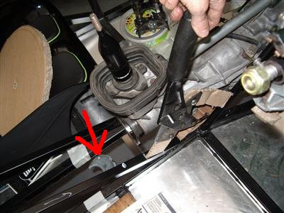
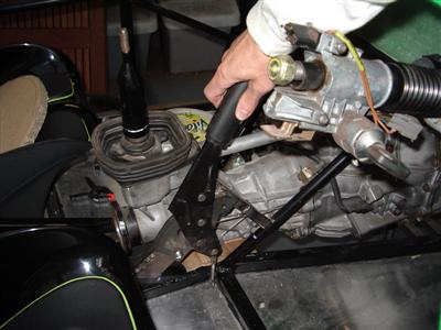
The above shows the position, with a cardboard template that I used to make up the bracket. The metal horseshoe (arrowed) is the bit which holds the rear cable. So the cranked linkage needs to go from the bottom of the handbrake, around the bracket, and connect to the horseshoe. I'll also need to modify the handbrake itself and move the connection for the linkage further round, since it's now all shifted nearly 90 degrees. I think it'll work...
Well, so far (and after one false start), I've removed the standard handbrake mounting lugs, and drilled new holes. It's handy having a spare one in case I cock it up! I did try heating and bending the lugs back straight, but it cracked. The steel is rather harder than mild, and it also wore out two drill bits. No worries though, there's plenty of spare material in it.
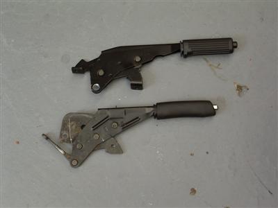 Top - unmodified. Bottom - lugs removed, new holes drilled.
Then I made up the bracket. Twice, because I measured the first one wrong etc etc. Need to drill the mounting holes, but you can see the idea:
Again, I did some test pieces first. It's 16mm box section and 2mm plate. To test, I welded bits of the box section together in various shapes, put it in a vice and hit it with a 4lb lump hammer. In every case, the box would buckle or collapse before the welded joint gave way...and I don't think I'm going to be able to pull on it with that much force. So it should be plenty strong enough. What is going to be fun is panelling it all in...
09 September 2009
Nearly a month since my last entry, it's that time of year for holidays, weddings and generally not being at home much. So there's been little progress to report.
What I have managed to do is to attach the handbrake to my bracket, and weld an extension on to the lever to move the attachment point (where the cable is attached) around a bit. This is necessary because the lever will be at nearly 90 degrees to its normal position, so the normal attachment point is now in the wrong place. I've also built the solid link to join the handbrake to the cable. I was rather pleased with the new shackle and handbrake adjuster bit:
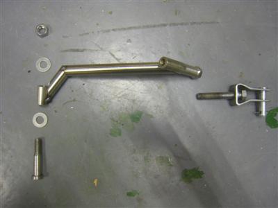
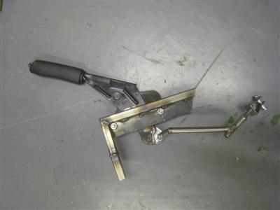 Left - fabricated pivot pin, link, and adjuster. Link just tack-welded together at the moment. Right: Attached to the handbrake.
The shackle is just a piece of 3mm steel plate bent into a difficult shape. The adjuster is a piece of stainless bar, drilled and tapped to M8, with a nut welded onto the end. I then had to turn it back down in the lathe to smooth off the weld, and tidy up the flats with a file. A long bolt then holds the shackle into the adjuster, allowing the length of the whole thing to be changed by turning the bolt.
Unfortunately, when it's all put together, the solid link imparts too much vertical motion to the cable, and it's dragging everything along the underside of the chassis. Ideally, it could do with a horizontal guide level with the cable to keep everything moving in the same plane.
So I'm back to having a bit of a think. I could just make a longer link, so that the vertical motion doesn't reach the underside of the chassis; or I might try a slightly different design with a horizontal guide attached to the chassis. To be honest, I'm not really bothered if it takes me a few goes to get it right, it's all good practice with different techniques and materials.
21 September 2009 - New motion - completely new motion.
So I had a bit of a think, and decided that the whole solid link thing was going to be a bit rubbish. Instead, I looked at what I could do with the existing front cable. Bringing it out from the back of the handbrake as normal just isn't a go-er; too crowded, and it would require too many bends - not to mention having to run around the propshaft, which didn't seem like a good idea. However, if it came out of the front of the handbrake, it could run in a very similar manner to how Dax do it; just instead of the end running up under the steering wheel, it bends down the side of the transmission tunnel.
All well and good, of course, except that the handbrake doesn't work that way round; I'd have to find some way of reversing the motion, so that pulling back on the lever causes the end of the cable to move in the same direction.
Cue lots of cardboard models to get the pivot points and linkage shapes I'd need. After a couple of nights of playing around, I'd worked out a linkage which would give me a complete reversal of motion, with a slight amplification. It didn't look like it would be too complicated, although did require making a new support bracket for the handbrake.
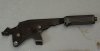
So a couple of weeks of cutting, welding, drilling, shaping, and turning, and I have a fully-functioning reverse-acting handbrake:
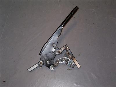
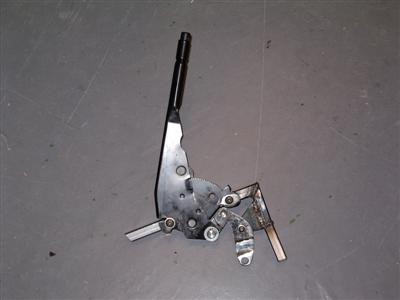 The cable will come from the right, and attach at the hole at the bottom right of the linkage. These two pics show how the action of the lever is reversed
The two parts of the linkage are made of welded 3mm steel plate - if I was feeling posh I guess I'd get something machined out of ally, but I don't have a milling machine. It's worth mentining that flap wheels in the angle grinder are incredibly good for shaping curvy bits of metal. I turned up the four pivots on the lathe out of stainless bar - the fixed one is screwed into the bracket, the rest are located with circlips. Where anything bolts to the bracket (the handbrake itself, and the fixed pivot), I've welded the nuts on - I think they will be quite innacesible with a spanner. It's also worth mentioning that the nuts seem to deform slightly when welded - I'm guessing because they are stainless, and the braket is mild, so they probably heat and cool at slightly different rates. This means that the thread deforms slightly and becomes very tight, but a quick run through with a tap made them good as new again.
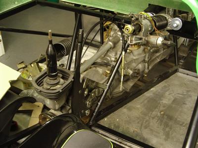
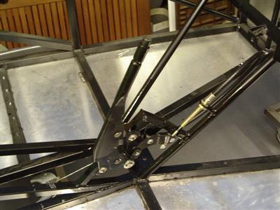
Here it is in place; you can see the cable hanging down the chassis rail. So it all looks like it should work.
What I have to do now is finish and paint the handbrake linkage to make it look less "scrapheap challenge"; releave the bracket slightly as the cable is chafing on it; make a support for the cable to bolt to; then weld it onto the chassis. This last will need the gearbox (and hence probably engine) taking out for access. I'll probably also need to get some clips to hold the cable in place.
27 September 2009
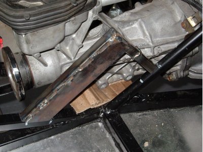
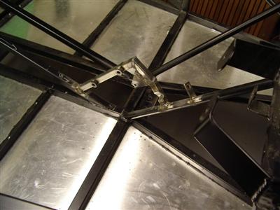
All of the above manged with no major difficulties. Getting the engine out with the box attached was very tight, not something I fancy having to do too often when the car is more built up. With that done, welding the bracket and cable support onto the chassis was not too hard - a bit fiddly to get at a couple of joints, but nothing major. I used magnetic welding brackets to hold everything in place, then tacked it on, before welding it all up properly. The pic below it just after welding:
A couple of coats of rustoleum black on everything, and it was time to put it all together in place and check that it actually worked. A slight moment of panic when the front cable wouldn't reach the connector on the rear, until I discovered that the rear cable was looped around the build stand. That aside, it all seems to work very well:
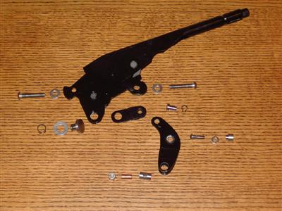
 All of the bits ready for assembly, and right, finally in place.
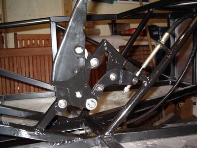
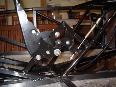 Close up of the gubbins. Released on the left, and pulled on the right. The mechanism slightly increases the amount of cable pulled, to the tune of about 1/4 inch
Really quite pleased with that. I've also recieved my gearbox mount and replacement rear quater panels from Dax, so I can get straight back on with the next bits.
While the design was good, I hadn't made the mechanism or pivot support strong enough, so it buckled the first time I used it. So I later had to redo it with heavier guage steel, larger pivots, and extra bracing welded on.