New Year, new Handbrake
25th January 2012
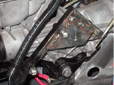
Before I get to the suspension and associated malarky, I had a bit of an issue with my handbrake mechanism. I connected it up to see how it would work, gave it a yank...it didn't seem to work very well so I pulled it on a bit harder...still very little effect. So I pulled it on harder still, at which point I realised something wasn't right.
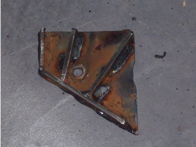
A quick peak showed what the problem was - my mechanism wasn't strong enough and had buckled and twisted, rather than actually pulling the cable:
In retrospect, it seemed obvious that it would have failed that way, at the time I thought I'd considered where all the forces would be applied. Yes, it's our old friend "experience" visiting again.
So there was little for it but to cut away the broken bits and remake them using thicker steel. I remade the support for the main pivot with plenty of bracing and with 5 times the attachment area, and the parts of the linkage with 5mm steel instead of 3mm. While I was redoing things, I redid the pivot pins and main bearing, all larger and stronger - the central pivot in particular being now twice as big. I also beefed up the support frame considerably as it flexed a fair bit.
Making the various bits took less time than originally, since I had the originals to work from. Doing the welding on the frame in the footwell was rather harder as space was very limited. So again I ended up with it being rather less neat than I'd have liked.
Anyhow, a few night's work saw me with a brand new handbrake mechanism. A good yanking on it convinced me that this time, it aint going to break (ha ha) this time.
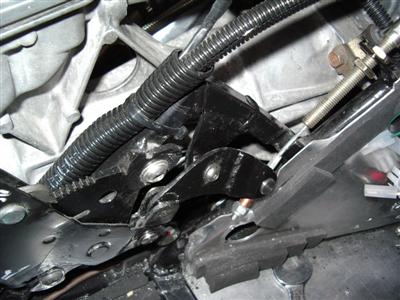
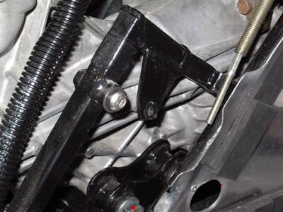
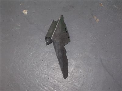
 New main pivot support - heavy bracing and welded to much more of the support frame
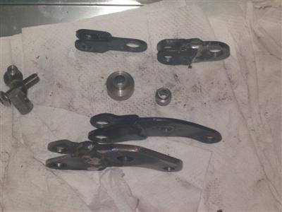
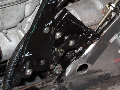 Left - comparison of the old parts with new, heavier versions. Right - all done and fitted.
Unfortunately it's not as powerful as I'd hoped. There isn't a huge amount of mechanical advantage at the callipers but there's not a lot I can do about that. By all accounts things improve when the pads are bedded in as well, so I'll keep fingers crossed.
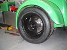
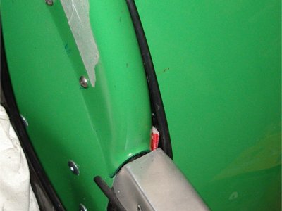
The final handbrake-related item was to provide some support for the cable as it wound around the suspension and driveshafts at the rear of the car:
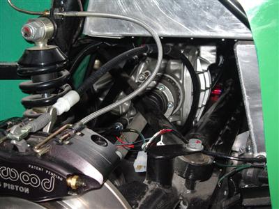
I asked on the forum, and with the standard ford callipers, the cable attaches at the rear, and so can be clipped along the de-dion tube. However with the Willwoods, it goes in from the side. So I elected to add simple stainless steel hangers, rivetted and bonded to the bottom of my boot tub (below, arrowed). A large p-clip bolted to these holds the cable in place.
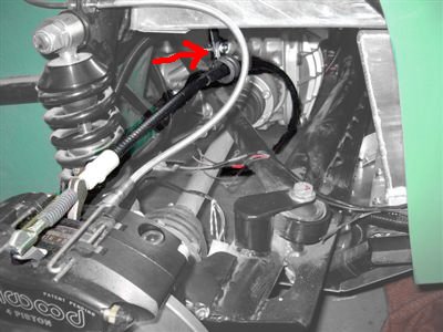
Crucial to note here is that the cable must be free to slide in the clip - because the callipers use a pair of arms to activate the handbrake, identical to a mountain bike V-Brake design, the end of the cable isn't fixed, but moves as the arm moves. Hence the clip is large enough to allow the cable to move a little. It still keeps everything nicely away from the flexi lines and the various moving parts of the suspension.
Suspension Set-up / Rear Arches
With the car on its wheels, a couple of things were obvious. Firstly, the toe on the front wheels was hilariously crosseyed, which made it hard to push around. Secondly, it's riding very high at the moment. This will be (a) because the car isn't at its final weight, and (b) apparently the springs bed in over the first few hundred miles and the ride height drops. The height was 185mm at the rear and similar at the front - nominal ride height is 135mm at the front and 150 at the rear. Experiments with putting a person in the car dropped the height by about 10mm, so by the time there's a driver, tank of fuel, and the additional weight of exhausts, fluids, etc, it probably won't be too far off.
However, I wanted to fit the rear arches, and to do this you really want to ensure that the wheel won't foul on them at full bump, and that they look right at nominal ride height. So I figured that I'd remove the roadsprings, and chock it up to the nominal height. At the same time, I may as well set the toe and camber (which has to be done at the correct ride height, as it changes as the wheel moves up and down). I'd also been advised by the ever-helpful folks on the Dax forum to slacken all of the suspension mounting bolts, and re-tighten them when the car had settled. This makes sense as it means that the bushes will be under zero strain when at ride height. Currently I'd torqued them all up on the stands, at full droop - so the effect would be to offer more resistance to the body of the car sinking down.
So over a period of a few days, I slackened the suspension, cleared away as much space as I could in the garage (which turned into a full-on tidy up), and rolled the car into position in the middle of the floor. I had to shim the nearside front wheel on a sheet of hardboard as the floor slopes a bit, and everything has to be level. Then I removed the springs (a miserable job - I hate anything involving spring compressors), and lowered the car onto wooden blocks to give the correct ride height front and rear.
While doing this, I noted that I'm definately going to need a new sump! At ride height theres about 1" of clearance, at full bump it's on the deck. So that answers that question.
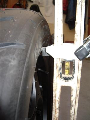
Also noted that, at ride height, the dampers are sitting just on the bump stops, which seems a bit wrong:
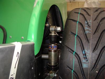
A quick search on the forum revealed much discussion about this. General consensus is that it does seem a bit wrong, but apparently it's taken into account in the suspension design, so I'll not worry about it.
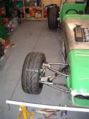
I first set the toe using the string method. That is, get two poles (I used plastic waste pipe because it's cheap), drill a hole at each end and tie lengths of string between them. The resulting frame is then supported at wheel-hub height to form a rectangle around the car. You then line it up with reference points on the car (chassis points, rear wheel hubs, etc), which aligns it square with the car. You can then measure the difference between the string and the front and rear of each front wheel, to determine the amount of toe. Obviously the steering wheel has to be centered first!
Easy enough. Camber is next. I did consider making up a guage (there are various plans on the internet), but I ended up just using a builder's level with a ruler taped to it. A bit of trigonometry (the camber angle is known, as is the distance across the wheel rim, so the distance from the top can be calculated - in my case it came out as 9mm to give the specified 1.25 degrees of negative camber.
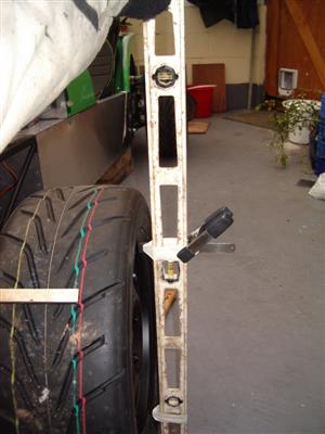
 Home-made camber guage. The taped spacers top and bottom are just to give clearance from the tyre, and bear on the wheel rim. The ruler is set to give a calculated distance at the top of the rim which equates to 1.25 degrees of camber
Camber is adjusted by means of shims on the top balljoint shank - they can easily be accessed by undoing the bolt and jacking up the car, the joint then can be pulled out:
Not sure how accurate I've been, but it looks about right, and it was certainly a great deal easier to push around when I refitted the springs! I'll be getting a proper professional suspension setup done anyway, so it only has to be about there.
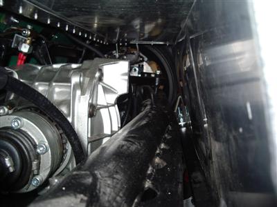
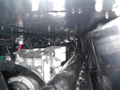
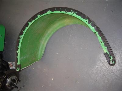
Just for interest's sake, I took the following photos of the de-dion tube at normal ride height (left) and full bump (right) to give an idea of what clearance there is in the back:
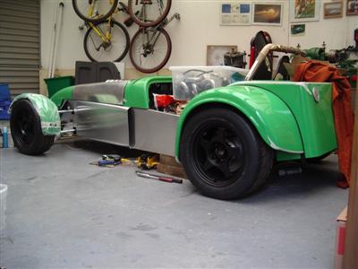
Before I could put it all back though, I had to do one final job, which was to work out where the rear wheel arches would go. These have a reputation for not fitting very well, which doesn't seem wholey undeserved, but also doesn't seem quite as bad as I'd expected. First thing I did was to drop the rear of the car right down onto the bump stops to give the absolute extreme of suspension travel. Then I fitted the arch using clamps, until there was just the smallest amount of clearance. This position of the top of the arch matched the rough measurements given in the manual, which I took to be a good thing. I jacked it back up to various heights to check that everything looked ok and that nothing would foul. I did this several times, moving it slightly to try different positions until I was happy, then tacked it on with a few clekos. Then did the same the other side, taking care to make sure it all looked symmetrical.
Then I could torque everything back up, refit the springs, and push the car back to where it normally sits. Obviously worth doing, as the suspension had sunk by 10mm all round - presumably just due to releasing the tension on the bushes, but that only leaves me an inch to high, which sounds as if it'll disapear as more weight gets added and the springs get a bit of running.
Next job then is to bolt the arches on. The hardest part will be trimming the join where the arch, rear tub, and side all meet. Going to have to have a bit of a think about that...
Fitting the Rear Arches
20th Februrary 2012
Nearly a month since the last update, it's been that snowboarding time of year again. In addition, my staring at : working on the car ratio has been especially high of late.
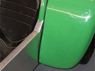
I must have spent hours in total checking the arch position. My previous comments about them not being too bad a fit were all wrong, they're hilariously bad. They do fit well, but in a far too low position - given that the moulding pattern must be a good 20 years old by now, I wonder if they were originally designed for smaller wheels/tyres, and hence were meant to be fitted lower down? Whichever, to fit them to clear the current standard size of tyre, you end up with a dirty great gap:
It's quite hard to show in photos how bad it is - but it looks really obvious in the flesh. It'd be much easier to get away with on a black car, but against the bright colour of mine, it shows up like a gaping chasm.
So I was thinking about what to do about that, and also worrying about whether they were too high. Would the suspension ever compress as much as I'd done with the springs in? Was I being overly cautious, would I end up with massive wheel arch gaps that everyone would laugh at? But equally, I'd hate to have to jack the ride height up later because the wheels were rubbing. I went as far as loading the car with weight to compress it down to ride height again, just to check that it looked ok.
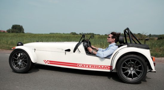
In then end, I read an old comment on the dax forum which pointed out how high Caterham arches are, and I don't see anyone saying how silly they look:
Now this probably seems all very "meh" to the reader, but when you're sat in the garage wondering exactly where to drill the holes, a centimetre here or there suddenly becomes very important! Anyway, after several days, I eventually convinced myself that the height was fine, and set about bolting it all on.
This is not as easy as it might be, because of various bits of chassis getting in the way, but I settled on M8 bolts bolted through the arch and rear tub where possible, with a few M6 rivnutted in where I couldn't get enough access, and one M6 on each side at the front tapped directly into the chassis. Big penny washers used throghout to spread the load.
A strip of wing piping goes between the two to neaten it up, and looks rather good. I've wurthed mine to the arch, so that I don't have to worry about getting it in the right place when I take the arch off. Which I'll be doing a few times yet I imagine...
So that left the dreaded gap to fill. I wondered if I'd get away with just fitting a pair of kick plates, but on balance reckoned that it would still look a bit naff. So I played about with some cardboard, and came up with a cover plate design which looked as if it might work. The usual two attempts at making it in aluminium followed, before I made one I was happy with:
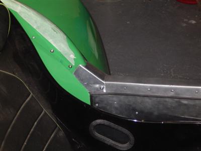
Again, this whole process involved much staring and trying out different ideas, until I settled on this one. I'm pretty happy with it, it blends in quite nicely and covers the hole without shouting about it.
So after all of this, I had one arch on. Now to do it all again, which is (a) easier, because I've got one to copy, and (b) harder, because they have to be symmetrical. And, oh, didn't I mention, the two mouldings aren't. Symmetrical that is.
So it's a bit of a juggling act, and you have to find the bits where people can see both together and make sure they look right from those angles, and loose the asymmetry in the places where you can only see one at once. It's not hugely bad, just a centimetre or so difference, but while I was moving things around, I reckoned that things start looking "off" when one side is about 5mm different to the other.
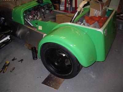
When I thought it was right, I cleared the garage and rolled the car out so that I could get a good look at its hind end, which is where you really don't want things looking wonky:
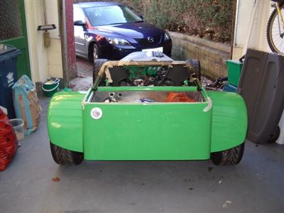 Does my bum look wonky in this?
So I need to make another aluminium cover, bond the wing piping in and on it goes.
I've also been having a think about how to proceede, and I think I'm going to work forwards from the back. That way, I should be able to fix things down permanently as I go, and hopefully shouldn't cost too much, giving me a chance to save up for the expensive bits at the engine end. So next step is rear lights, and speed sensor/speedo, then I can get the rear tub and arches all fixed. Then I'll get the propshaft, and will be able to fix the tunnel down. Then the dash, carpets and trim etc, then the rest of the engine bay.
I've also got a number of scratches, cracks and moulding flaws I'm not very happy about. Some I've caused, a couple of cracks seem to have just developed, and some are manufacturing defects. I guess I could get the latter bits replaced, but I'd still need to fix the rest. I need to decide whether to get the offending bits resprayed or just to try gelcoat repair. I'm leaning towards paint, if only because I will be making a bonnet bulge, and will need to get that painted. So some research to do there.