Pretty colours, hurting brain
Engine Wiring, Brakes, and other things...
8th November 2011
The next job I thought I might tackle is having a look at the engine wiring loom. Just before I did that though, I cleaned up the fuel rail and fitted that, just so I can better see where all the bits might have to go.
Fuel Rail
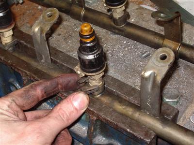
All I did was remove the injectors, clean the rail, paint it, and replace the bits of rubber fuel hose which connect the two parts. The injectors will need replacing with higher rated ones anyway.
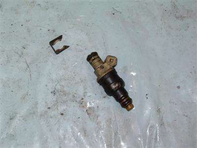
Simple to remove - slide off the clip, then they are just held in with a tight-fitting O-ring, so can be pulled out with a twisting motion. A squirt of plus gas made removal lots easier.
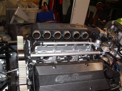
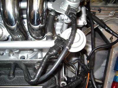
Again, obvious if you've done it before, but not if you haven't. Below is the rail back on the engine. I'll need to get some connectors for the fuel line, and it'll be all plumbed in.
Engine Loom
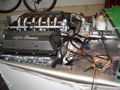
So here's the original loom:
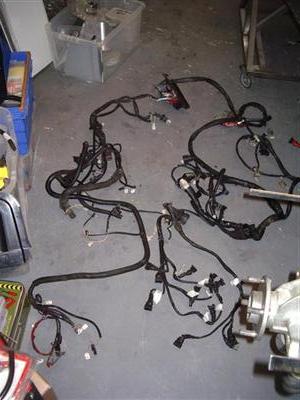
It's times like this when carburetters seem like a good idea! Although I'd tagged every connector on the loom, many of the corresponding tags on the sensors had become illegible - sitting in an oily box for a couple of years will do that, apparently. Take note - use pencil, not ballpoint. Anyway, offering it up to the engine it soon became clear what went where.
The loom is actually in two parts - there's the injector loom, for want of a better phrase, which is attached to the heads and connects to the injectors and coilpacks. This then connects to the rest via a rather nice twist-lock connector (arrowed below). The valve covers have moulded lugs which hold the loom in place. I thought I'd tackle this first, as it's simplest.
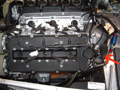
A bit of prodding with the multimeter showed me how the loom was arranged. Each coilpack has a signal wire, and there's a common live and earth. For the injectors, there are two sets of three wired together - so they must be firing in batch mode. If my maths are right, that means that each injector would fire 3 times per revolution, rather than just when the inlet valve is open.
The coilpacks are then connected (on the main loom) to these fellows:
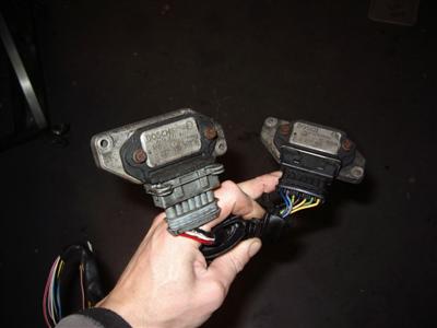
A quick google of the part number on the side informed me that they are Ignition Modules, Bosch 0 227 100 203. I'm not entirely clear on the electronic side of things, but they provide the ignition signal to the coils, by some magic.
Not sure if I needed them with an aftermarked ECU, so I fired an email off to Emerald (which is the ECU I'm planning on using). They replied quickly and told me that the ECU could fire the coils directly, or use these units, and it really didn't make much difference in terms of performance. So since I'd slightly cut the loom (by which I mean, completely severed) where it feeds these (overzealous when I was taking it all apart), I think I will ditch them.
The other thing I learned from reading Emerald's site is that it's preferable to wire each injector individually. Then the ecu can be programmed to fire them batch, or sequential (once per revolution). So I will modify the injector loom by adding in new wires for each injector. There are plenty of spare ports in the main connector, and I managed to locate some crimp-on pin connections (from a thing called a "Neptune Connector) which seem to fit.
The connector ends are covered with rubber boots. While the connectors themselves (referred to as "junior power" or "mini timer" connectors) are in good nick, the boots are all perished:
These can be replaced, but to do it, I'd have to cut the connectors off and fit new ones (I tried removing the pins but couldn't - I've managed on some other connector types but these seem quite impossible). With new connectors and boots at over a fiver a go, I'd be looking at 70 quid or more for the lot. So I think they'll have to manage with loom tape.
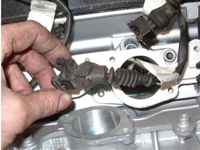
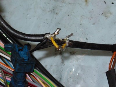
Another bit I'll need to replace is the main lead to the crank angle sensor. This is a shielded cable to prevent noise interfering with the signal, but at some point has had a rather dodgy repair done to it:
Brakes, again
16th November 2011
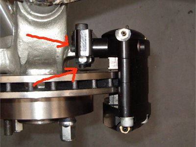
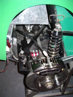
All my new bolts arrived, so I fitted the callipers for real. I'm much happier about the amount of thread engaged now:
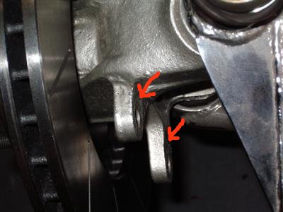
When I torqued them up, I still had issues with the fronts. The callipers weren't quite square with the disks. I dismantled and remantled several times, but to no avail. Eventually I worked out that it was actually the thick PQR-15 paint on the hub lugs where the calliper adaptor mounts (below). A couple of blobs of paint were thick enough to mean that the mount wasn't sitting square, and so the whole assembly was canted over. Only a tiny amount but enough to make quite a difference where the calliper meets the disk. To resolve, I filed the paint off the mounting lugs, back to bare metal, and the problem was solved. Strangely it didn't cause problems on the rear hubs, perhaps it was the angle they dried at which caused the paint to pool in a particular place on the fronts.
Almost there...but the passenger side calliper was just catching on the disk. More dismantling and head scratching. I measured the disks and they are a smidge under 283mm across, so that wasn't the problem. Looking more closely, the clearance at one end of the calliper is about 0.5mm, and at the other is "gnat's chuff". It's the same on both callipers:
So on the driver's side, there was just enough clearance and the disk didn't touch. On the passenger side, there was just less than enough. We're talking tenths of a mm here. It seems to me that this means that the mounting holes in the adaptor are about 0.5mm out, and should really be a bit closer to the end with the most clearance to even it out.
I toyed with the idea of taking a couple of thou' off the disk, but it was going to be a pain to mount in the lathe - a two minute job to actually machine, but probably a couple of hours to set up. So in the end I just took the tiniest amount off the inside of the caliper using a fine file and emery paper, until the disk would turn without catching. And finally, I could threadlock it, tighten it all up, and say "done".
So my experience of the Willwoods isn't great so far...but from what I've been told of the performance, that should all be forgotten when it's up and running.
Brake Lines, again
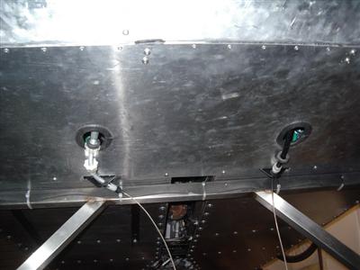
During one of my "giving the car a good staring at" sessions, which are frequent, I realised that there really wasn't much space to get any air ducting into the throttle. Not the best angle in this picture, but it gives an idea:
To start with I had a sudden fear that I wouldn't be able to get any ducting in at all, but a quick bit of googling allayed that worry. What was a problem was the front brake line - it would be very close to, or even touching, whatever intake ducting I use.
Although this all seems a long way off, I will need to fill the brake system soon (before I get the wheels on ideally), and I don't want to be taking brake lines apart once it's filled with fluid. So time to sort it out now.
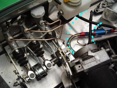
Simple enough in concept, I just made up a new line with a slightly different routing that will run under the ducting. Of course, it took three attempts and 2 hours to do. I'm very glad I made these top foot-long sections of line separate as I was advised, or it would have been a proper PITA. Plenty of clearance now between the new line and the (crudely drawn) route the ducting will take:
Handbrake Cable
I fettled the handbrake cable so that it fitted to the calliper. As I did so, I noticed that the rear undertray meant that the cable didn't sit properly - it needs to pass through the undertray rather than go around it. So I cut a couple of holes and edged with edge trim, and the lie of the cable is much better:
Wiring
And between all that, I've been making inroads into the wiring. I soldered some more wires into the injector loom (stolen from an unused bit of the alfa loom), and put plugs for each into the big connector. So now, each injector will have a control wire instead of one wire shared between 3. I then re-wrapped the loom with loom tape. At the ends of each connector, I've used two double layers of loom tape, which was time-consuming, but should keep the muck off.
So that bit was time consuming but fairly straightforwards. I've now moved onto the rest of the engine loom. I've had to strip it all down really to see what was going where, and it actually seems a lot simpler now it's all in pieces! It's really only a 2 or 3 wires between the ECU and each sensor, which is nice and easy. I'll want to put in some earth wires to make sure that the engine block, head, and valve covers are all earthed to the chassis, but that's about it really. I need a couple of new connectors to replace broken ones, then it's "just" a case of working out a neat routing for it all.
The harder bit is bringing everything together - running connections out from within the scuttle, and from the engine bay loom supplied by Dax. It's all a fair bit of work, but doesn't seem as scary as it did.