Engine Update
27th October 2010
First off, I had a word with the engine/cam people, and it's still going to be a couple of months before the pulleys etc are machined up. Hopefully they can get the pistons to me before the rest, so at least I can at least build up the short engine. I need that so that I can fit the engine and box back together, and measure up for the clutch and propshaft.
Fortunately, I'm not short of things I can do yet, but I am starting to do things I'd have expected to do towards the end of the build.
Tunnel Fitting
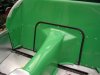
Now that I've got everything (bar the propshaft) fitted into the tunnel, I spent a couple of evenings finalising the fit. My main worry was where the tunnel meets the bulkhead, as the fit is very poor and left rather a large gap. This will usually be covered with carpet, but I want the green tunnel to be uncovered. Besides, "cover it with carpet" is a bit of a frig, if you ask me. Anyway, I ordered some edge trim to see how that would look. And turns out, I needn't have worried, it looks good, like it's meant to be that way, rather than an attempt to cover up a hole.
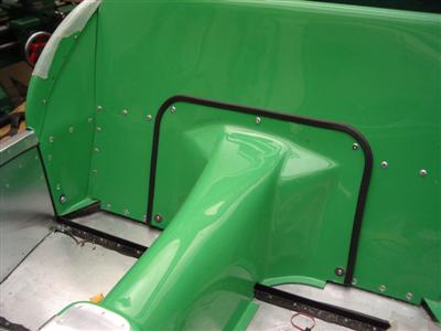
The tunnel doesn't need much in the way of fixing really, but I've put a few bolts in, as much to keep the edges flush as for holding it in. At the rear, two M6 bolts and penny washers at the bottom of the moulding hold it to the bulkhead, using rivnuts. These are the main anchors for location. Along the top, I've used more M5 furniture bolts - these are really just to hold the top edge down as it's a bit springy. I used the furniture bolts as they are almost identical to the big-head rivets holding the bulkhead on, so don't stand out. It'll all be behind the seats anyway, but attention to detail and all that.
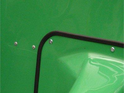
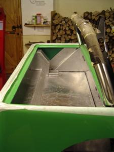
At the front, I'm reusing two bolts which hold the wiring loom onto the underside of the aluminium flange at the front of the tunnel. I've used extra long bolts so that they can pass up through the GRP moulding as well, so I've got bolt-pclip-aluminium flange-bolt-tunnel-bolt, if that makes sense. So I can unbolt the tunnel without unbolting the wiring. They're only M5, but it's really just a location device, I don't think it would move anyway.
I also used some smaller trim to just finish off the cut edge in the passenger footwell, this is glued on with silicone sealant (see below). To give the rather flexible moulding a more solid feel, I've used strips of self-adhesive foam (came with the kit) to pad out the front of the moulding, as there is quite a cap between it and the chassis (it would normally be much more solid because of the front flange, which I had to cut off...). With all this done, it's fixed very solidly to the car, and now feels like part of the structure, rather than a bolt-on cover.
 Arrows show the two long bolts holding the front of the tunnel down
Wiring Bits
Also did a couple of little bits of wiring - shortened the fuel pump wire and crimped on new connectors, and did the same for the horns. (I'm very much on the crimp, rather than solder, side of the "which method is best in cars" debate, because crimps is how they do it in production cars and aircraft). I have a decent set of ratchet crimps which ensure you get a proper crimp every time.
I've left the earth connector off of the fuel pump for now, so that it doesn't get started accidentally when I start powering bits of the loom up in future - these pumps don't like running dry and I don't want to knacker it.
I would have connected the brake light switch, but the wire aint long enough. I can't really see how it could ever reach, frankly, even if I routed the loom quite differently (though I have followed the suggestion in the manual anyway). I need to buy a couple of connectors to do that.
Boot
Thought I may as well make a start on the boot while I was working around the back. I've never planned to fit the standard boot box as it is tiny, more of a tray than a boot. I saw several cars the first time I went to Stoneleigh with custom made boots, and there is actually quite a lot of room in the back - easily enough for a couple of soft overnight bags.
I'm going to use 1.5mm ally sheet to make the boot, because I've got two big sheets of it I bought ages ago by mistake. It's a bit heavy, but then a boot gets things chucked and stuffed into it, so it's as well to have a bit of solidity. By my reckoning, I'll be using about 4-5Kg of the stuff, (GRP one weighs 4.5Kg so no difference really), so the saving of using 1.2mm would only be 1Kg anyway. It is a lot harder to bend though!
I started off thinking that I'd make a replacement box which dropped into the top of the tub, but after a few hours faffing about, and a quick chat on the forum, I'm going to go down the road of building it in place, then fitting the tub over the top. This will let me get the maximum room inside(as the hole in the top of the tub is rather smaller than the inside of it). It'll mean I have to take the tub off to get at the top of the diff etc, but that shouldn't happen much, if at all.
Intermission
November-December 2010
Building's off for a couple of months, unfortunately, because of the dreaded d-i-y. That said, with temperatures getting down to -13 at night, and -6 during the day, the garage isn't an appealing place at the moment!
Back in the Boot
January 2011
A Happy New Year to anyone reading! Finally, after all the decorating and Christmas is out of the way, I was able to tidy a path through the debris, uncover the car, and try to remember who I was and what I was doing.
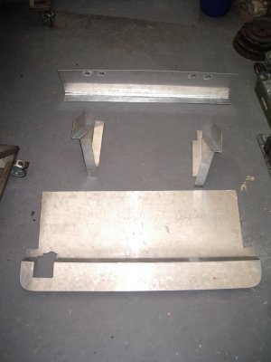
So, the boot. I ended up making this out of four pieces; a floor, a front wall, and two side pieces; the back will just be the inside of the tub. Nothing too clever here, but I've lost count of the number of trial fittings I had to do to get everything cut to size. I'm certainly bored of putting the tub on and off.
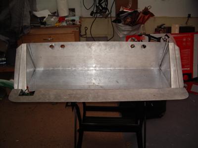
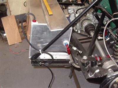
These parts are then riveted together into a single insert, which goes in on top of the fuel tank - I've used more of the sticky rubber strip between the two to prevent fretting. I've bolted the top edge of the insert along the main horizontal chassis rail with M6 bolts. I didn't use rivnuts here, because it's a large, thick-walled member so I could just tap threads straight into it. The side pieces will also be bolted through the rear tub, but that will have to wait until the mudguards are on.
To secure the very rear edge of the aluminium floor, I made up some brackets from aluminium angle, and epoxied them into the rear tub:
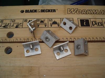
Unfortunately, the cold weather scuppered me - when I fitted it all together the next day, half of them just broke off - the epoxy hadn't properly cured in the cold. So they are currently sitting in the back bedroom, having been re-glued.
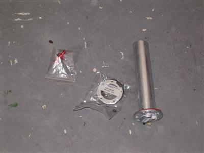
The other complication at the rear of the floor is the fuel sender and filler tube on the nearside, and tank breather on the offside. The floor needs cut-outs to clear these, then they will need boxing in. And before doing that, I really needed the offending parts so that I know exactly how big they are, so I got them ordered.
I'm getting the fuel cap and filler from Dax as a standard set, largely because it didn't seem much different in price from buying bits, and secondly because I got bored trawling catalogues of fuel pipes. The tank is plumbed for a breather valve, (the standard Dax one just uses an open hose). I've gone for one which allows air in and out, but blocks fuel in the case of a rollover. Finally, although the kit comes with a standard sierra fuel sender (which you have to bend about to make fit), I had my tank fitted for a VDO dip-tube sender. These are supposed to be much more reliable (less prone to fuel sloshing about etc). More expensive of course!
One thing to watch out for when fitting the sender is that the screw holes are assymetric, it'll only go in one way around. Isn't obvious at first glance though, for a horrible moment I thought that the holes had been drilled incorrectly. I also bought a fitting kit, which it turns out I didn't need - it's only needed if you don't have threaded bolt holes in the tank. With it fitted, I spend an hour or so fixing the rear part of the wiring loom in place, making sure it's not going to chafe anywhere etc.
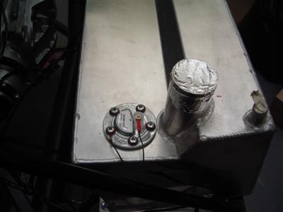
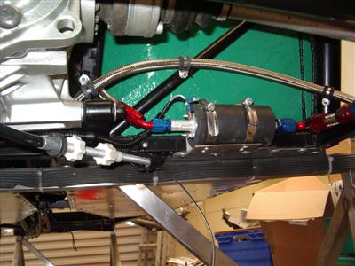
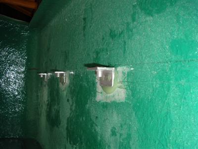
The breather valve just screws in, no mystery there. I've run a hose from it (small red thing in the top left) down and out of the bottom of the chassis as shown - just in case.
Haven't got the fuel filler yet, but when that's arrived I can fit it all, box everything in, and the boot will be basically finished.
Pistons
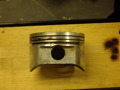
The pistons arrived back in November some time, with new larger inlet valve cutouts:
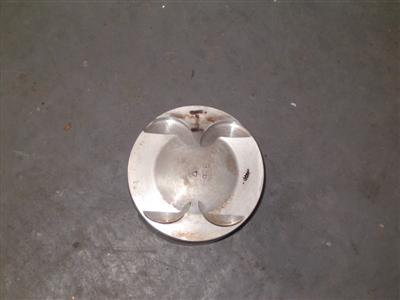
I didn't have time to clean them up before I sent them off, so before I do anything else, I need to clean out the piston ring grooves, with my newly-aquired piston ring groove cleaner:
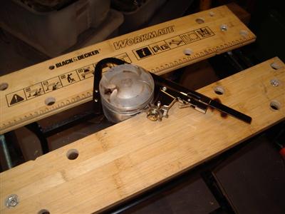
Quite simple, it just hooks into the groove and you run it round and round to clean it out. BUT, there was a bit of a high point on the "hook", which left scratches around the piston the first time I used it - a quick rub with emery paper solved that, so worth a check before hand. The dirtier grooves required a few goes to clean out all the clag, so it took well over an hour to do all 18 grooves, which was fairly tedious. Obligatory "before" and "after" shots below:
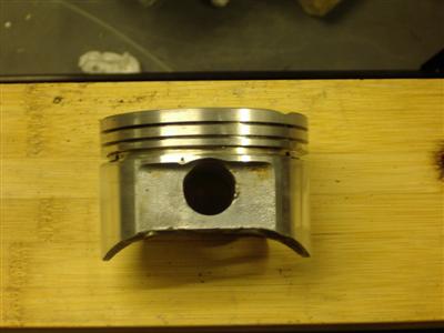
Mmmm, shiny. It's occured to me that I need to source some more circlips for the gudgeon pins before I can stick it all back together (I'd left one in each piston, but the machinist removed them and advised getting new ones - or maybe lost them, who knows. Either way, I need some more).
Fuel Filler
19 January 2011
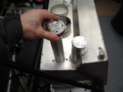
My fuel filler cap and bits arrived, so I was able to get on and fit that. Fairly simple, cut a hole in the tub and the cap screws into it. The one oddity is that Dax weld a breather connector onto the fuel filler cap (to let air out when you're filling up). This makes getting the cap through the hole a bit tricky:
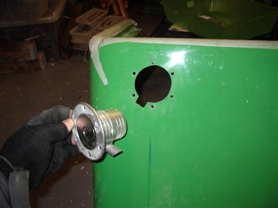
Through a combination of cutting down the breather connector as much as I dared, making a cutout for it in the tub, and ovalising the main hole (you can see in the pic it's extended towards the top right), I was just able to get it through. It looks rather good in place, unfortunately I didn't take a picture it seems. Have to put one up later.
So with the cap in place, the main filler and breather hoses could be cut to length and fitted. My next step was going to be to box it all in, and the boot would be finished, but fate intervened...
Crunch
The next night, I went for a snowboarding session at my local indoor slope. All was well until I had an awkward fall from a railslide, fell onto my right hand and dislocated one finger and seriously bashed another. Proper job, it was all sticking out at a funny angle. Now I'd done something similar some years ago, and spent 6 hours in A&E with a mangled hand. I didn't fancy staring at it for several hours again, so I grabbed hold of it and popped it back in myself. And yes, it did hurt. Quite a relief afterwards though. Anyway, it's rather limited what I can do on the car for week or so - rivetting, sawing and filing in particular are not really "on".
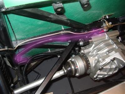
So I did a couple of odd bits - wired in the brake light switch, which as I mentioned before required an extension to the loom. Be nice if it "just fitted", but whatever. I used inline crimps to connect the new longer wires, with heatshrink over for added support. Crimping the connectors on was fun, with one hand in a confined space... I wrapped the wires in loom tape, then put covoluted sleeving over the lot, and held it in place with a few p-clips. I tested it with a multi-meter before all of this, to make sure that my connections were good. The new wiring is highlighted in purple:
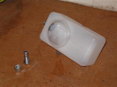
I also blanked off the clutch feed from the hydraulic fluid resevoir - since my clutch cylinder has a separate resevoir, I don't need it.
The feed is just a hollow bolt which is bolted into the side of the resevoir. I just replaced it with a cut down solid bolt of the same diameter. Below, you can see the new bolt in place, with the old hollow one in on the bench.
Boxing in and Finishing Off
26 January 2011
Some 10 days after my finger mangling incident, it's all still rather swollen and sore, but seems to be gradually getting better. It stopped hurting enough that I could get on and do a bit, albeit using my left hand for some tasks, squeezing the riveter particularly.
It meant I could finally finish the boot, by boxing in the fuel sender and filler pipe. This was yet another bit of aluminium bending to do, to form the cover you can see below.
I actually managed to make it a little narrow - when I fitted it, two the bolts which hold on the fuel cap were fouling it. An easy enough mistake as they are tucked right out of site under the lip of the boot tub, and I just missed seeing them. Rather than cut clearance holes, I used a drift to bow out the aluminium into two blisters - a neater solution, not that it's visible.
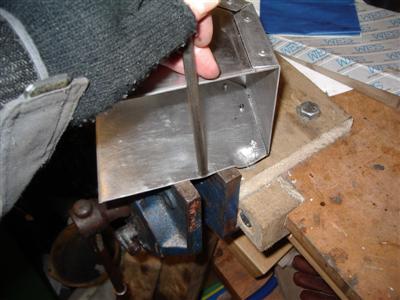
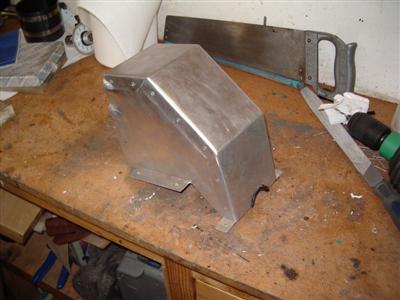 Left: Rectifying mistakes with my friends Mr. Hammer and Mr. Drift. Right: The finished cover - note the blisters on the left hand edge.
The semi-circular hole at the bottom edge is for the fuel sender wire to pass under, which is why I've used rubber edging to prevent chaffing.
The cover is bolt on, rather than being rivetted into the boot floor. This is because access is required to the fuel filler pipe to get the filler cap on, so the cover has to be removable in case I ever need to take the boot or rear tub off. It would be oh-so-easy to rivet things like this in place, then have no way of getting it all apart again.
With that done, and a bead of wurth run around the seams to make it all watertight, the boot is finished:
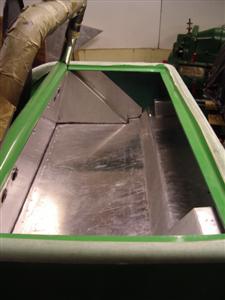
I may put some carpet or rubber matting in it when I get to that, and a few loops or hooks for attaching cords or luggage nets will probably find their way in there later as well.