Fuel Lines
12 October 2010
So my fuel hardware arrived last week, and I was able to set to putting some bits together.
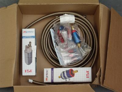
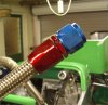
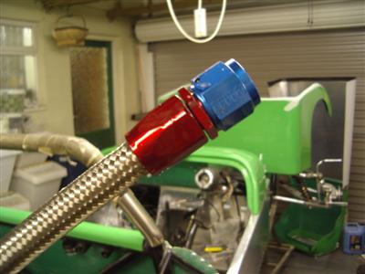
For the record, I'm using -8 sized hose for the feed to the pump, and -6 for the high pressure and return lines. (The "dash" numbers are the JIC standard, and represent 16ths of an inch. So a -8 hose is 1/2 inch inside diameter.) I've got a Sytec "bullet" filter to go in front of the pump, and a smaller sytec lightweight filter to go after it. The pump is an FSE facet TCP020/3, with -8 input and -6 output, all the hose is Aeroquip AQP, and the fittings are Aeroquip.
For pumps and filters, I've mostly I've just copied what other people have used, though I did check that the pump would flow enough for the engine using a calculator I found online.
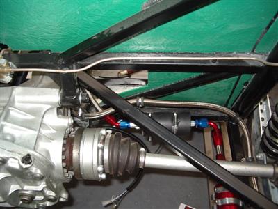
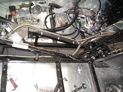
The first thing that became apparent was that the aeroquip fittings are huge, especially the -8 ones, are very large, and very long. This lead to the first problem, which was where to put the bullet filter. The normal place is on the rail which runs back from the bulkhead to the fuel tank. However, it would be impossible to mount the filter so that it didn't hang under the chassis rail, because there's so little clearance under the de-deion tube when the suspension is in droop. (below, left). The other possibility was directly under the fuel tank; this is raised up so gives more clearance. (Below, right)
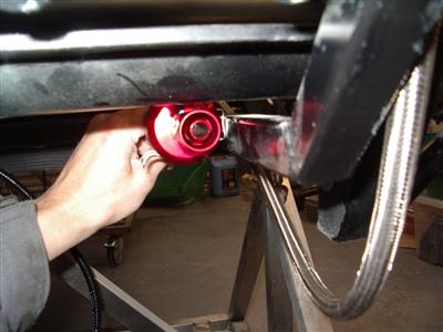
I actually did fit it in the second position to start with (and was having a bad day...never have I drilled so many holes which weren't quite in the right place. Made a right mess.) But then, I decided that it was hanging out the back far too much. It was going to make fitting the tub (and undertray) very hard indeed, plus I want to keep as much out of the overhang as possible, as we have a steep drive to the house and I'm a bit worried about grounding out. So I checked what others had done, checked the IVA manual, looked on lots of forums etc, and found that there is nothing which says that everything has to be above the lowest point of the chassis (which is what I assumed). So having the filter protrude slightly shouldn't cause any test problems, and in the end I moved the filter back to position one.
Of course, it's not about passing the IVA, it's about it being safe. But after much staring and thinking, I think that the odds of bashing it must be very tiny. The protrusion is 15mm, with about 10mm clearance to the de-deion tube when the suspension is in droop. I probably worry too much to be honest.
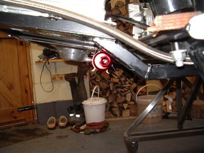
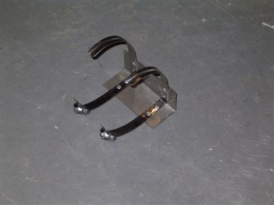
With the filter mounted, the next step was the pump. This just came in a round rubber sleeve, so a bracket had to be made. I used 1.5mm stainless again, and rivetted two stainless jubilee-type clips to it to hold the pump. The whole thing was then rivetted to the frame behind the driver's seat, with big head 5mm rivets.
Making up the Hoses
Making up the lengths of hose was "fun". There were a couple of times when I was wishing I'd just used ordinary rubber hose, though I'm glad I went for this in the end.
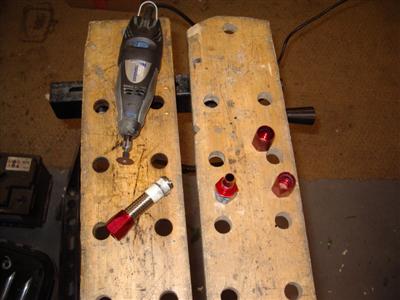
The main thing is to cut the hose without the braid fraying. Apparently you can use a "fine toothed hacksaw", but, just, no. After a few failed attempts, I found that a cutting disc in the dremel was the way forwards - wrap the hose with tape first. I found that self-amalgamating electrical loom tape worked very well. Masking tape is good too, but makes everything sticky.
The cut end then has to be inserted into the outside collar of the fitting. (I washed then ends out with white spirit first - I'll need to flush the hoses with petrol before final fitting.) This is hard. Any slight frayed bits of braid will scupper you. Then, the inside of the fitting goes inside the hose and it all screws together. You must lubricate the inside or you will be scuppered - 30wt oil , or they sell a special lube. A vice and a big spanner is needed to screw it down - I was constantly worrying that I was going to strip a thread, it takes a surprising amount of force, but they were all fine.
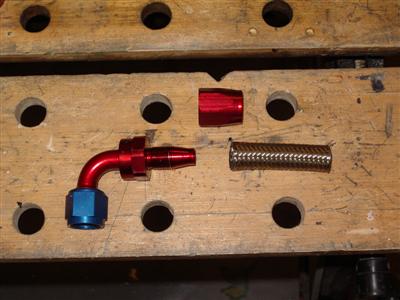
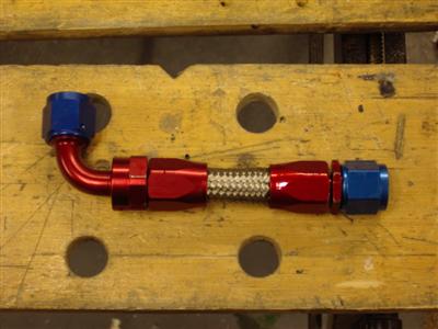
After the first few, it gets a lot easier. And they do look the business, and seem very secure indeed. Shame no-one's going to see it all, really...
Fixing the Hose
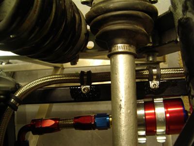
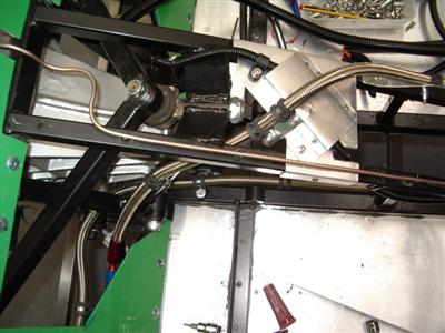
With hoses made up, I could start fixing them to the chassis. I'm using "Mikalor" rubber-lined p-clips, held into the chassis with steel rivnuts and stainless cap head bolts. Easy enough stuff. The return goes above the pump and down the outside of the chassis rail, I've clipped it often as it goes under the suspension because there isn't a whole lot of clearance around there, and I don't want anything flapping around, even slightly.

Down the Tunnel
Next job then is to run the hose down the tunnel. I still haven't quite decided how to do it yet - run them high, out of the way of anything like snapping props? But then they are impossible to inspect, and any leakage from a perished hose might run down and collect inside the cockpit. Or run them low, so that any leakage will drip safely away, but the risk from other damage might be higher? There's also cables, brake lines, the diff and gearbox to route around...space is just very limited, it's a pig. Perhaps the biggest downside of these braided hoses is that they are very thick.
21 October 2010
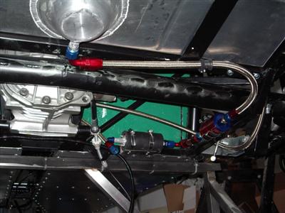
So turns out I had to do it both ways - send the high pressure line along the top rail, and run the return line along the bottom one. I couldn't fit them both in the same routing, bits of chassis / tunnel moulding / brake line / electrical cable always seemed to get in the way.
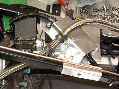
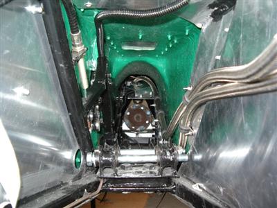
The high pressure line runs from the pump, up the outside of the support for the suspension A-arm bearing, basically the same routing as the electrics but on the other side. Unfortunately, this means that the electrics and fuel line have to cross over. I considered re-routing the electrics, but there's no way I'd get the fuel lines up the driver's side at the front, because of my handbrake mounting. So instead, I made up a slightly crazy bracket from 1.2mm ally, which (a) gives me somewhere to clip the fuel line as it feeds down through the chassis members, and (b) has a cover to keep the electrics separate from the fuel. This of course meant undoing that whole run of cable which I'd only recently done. I also had to buy a 45 degree connector to replace the straight one for the pump output.
Also in the picture above, you can see the return line passing under the diff. I tried several ways of running it alongside the high pressure line, but clearance between moving bits of suspension / the propshaft wasn't great, and keeping the lines themselves from chaffing against each other would have been all but impossible. One of these attempts is shown below - looks ok like this, but there wasn't room to get the tunnel moulding over the top - the lower line was stuck out too much at the rear (area shown in red). Equally, they wouldn't both fit under the diff, not on the one side anyway.
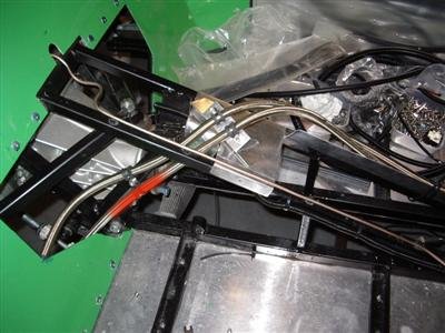
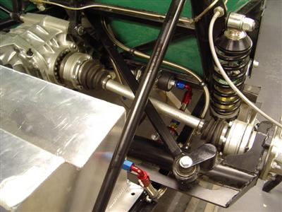
So, from there, the high pressure line runs down the top rail, and the low pressure one along the bottom rail. I made up a simple bracket to clip the top line to, so that it wasn't sticking out near the propshaft. At the front, both come together, the low pressure line crossing under the gearbox, but (assuming my measurements are correct), there is plenty of vertical clearance there.
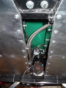
Had to be very careful around the gearbox mount, to ensure that I left space for a spanner to actually do up the mounting bolts!
And that's as far as I've got - partly because I ran out of clips, and partly because I want to have the engine in before I plan the final routing through the bay. Not entirely sure where to put the final filter yet - it needs to be accesible without having to remove the engine!
I've been careful to make sure that it will all come apart, so nothing rivetted on top of anything else that I might later want to remove. I'll also need to take it all out, well the high pressure line at least, to fit the end connector for the other filter (as it has to go in a vice). A bit of a pain, but I'll use the opportunity to flush the hoses through. When I finally assemble it, I'm going to locktight all of the clamp bolts to make sure everything stays in place. Where the hoses might touch something, particularly where it runs under the diff, I'm going to stick some convoluted trunking over the top for added protection.
This is the first part of the car I'm not really happy with. Despite spending ages fiddling and faffing around with it, I've been unable to find a routing which seemed right. This just seems like the least worst option. I'm not worried that it's dangerous or anything, it just feels like there should be a neater way to do it.
Earthing Points
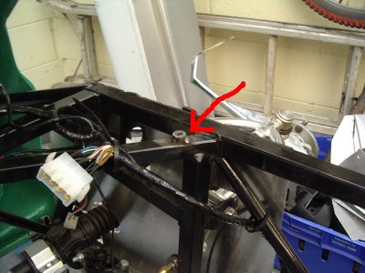
As mentioned previously, I've made up 5 (so far) little lengths of mild steel bar with blind holes in them, threaded to M6. They're 1mm deep, roughly the same diameter, with the hole about 8mm deep. I've welded one on each front corner of the engine bay; one under the scuttle; and one on each side of the fuel tank frame. Note that I removed the fuel tank first and placed it outside! It still smells a bit "petrolly" from being rinsed and I am taking no chances! These positions are just where the loom has earth connectors. I guess I may need another one or two for the engine loom, but I'll do that later if so.
A quick couple of coats of paint to finish, leaving the top surface as bare metal, and I should have perfect earths every time, without the risk of rusty holes in the chassis.
Back together again...
One of the most time-consuming jobs is the repeated assembly and disassembly that goes on. After all of that, I've put the rear tub back on, partly to check that none of the fuel hoses foul it (they don't), and partly because it's the safest place to store the darn thing. The scuttle also had to come off for the welding, then back on...and it won't be the last time either! But this sort of thing can easily take up a couple of hours of an evening without any visible progress to show for it.