Steering Column and Front Suspension
7th May 2010
Stoneleigh was good, if very cold, and I came away with a lot of pictures, ideas, and a spring compressor. I also spoke to Dax about the nuts for the front balljoints - having measured, the balljoints are actually M18 with a 1.5mm pitch - Simon at Dax tells me that they had a bad batch of nylocks which had a 1.25mm pitch, which is what I've ended up with. So they're going to send me a couple of the correct ones.
Alas, and as usual, the spring compressor didn't quite fit, because the springs used on the Dax are very small in comparison to normal road car ones - so I had to grind and file it some before I could use it. That done, it was an easy job to fit the springs under the top caps.
Since I seem to be progressing in a generally clockwise direction around the engine bay, I decided to carry on in that direction, and look at the steering column and driver's footwell panel next.
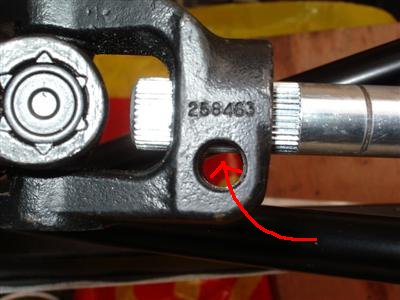
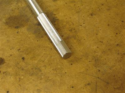
The steering column consists of the sierra column and two splined rods which are joined by universal joints. The columns are supplied overlong, so that they can be cut exactly to length. Easily done with a hacksaw, and I machined the cut ends square in the lathe. The other thing is that the splined end will need a flat filing in it to accomodate the pinch bolts:
So that all goes together easily enough. Unfortunately, it does go right through the driver's side brake line, which I've had to remove and will need to reroute later. The lesson here is, put the steering column in first!
I then spent quite some time getting the steering wheel's vertical position to my liking. I cut slots in the mounting bracket so that I can move it up and down by an inch or so. Once I was happy with it, I clamped it in place, and measured up where the column would pass through the footwell panel.
To do this, I used a trick I'd seen on the Locostbuilder's Forum. It's just using strips of masking tape to mark the position of the column, which is then removed. The panel can then be offered up and the masking tape used to mark out where the hole needs to go. Simple, but effective.
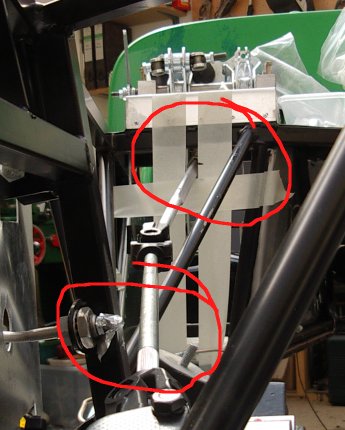 Top circle - marking out the position of the column with masking tape. Bottom circle - had to remove the brake line from here as the column needs to be in the same place!
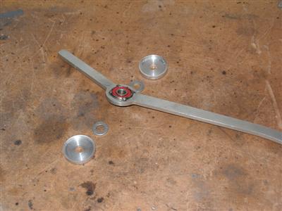
Making up the panel itself was fairly normal. As with the passenger side, you have to bend it quite severely to get it into place. The column is supplied with a flexible bushing mounted on a aluminium plate to be mounted on the footwell panel. I decided to make up a spreader plate for the inside of the panel to spread the load around a bit, then bolted it up with stainless M5 bolts and nylocks. I made the plate up with some of the spare 1.5mm ally sheet I had. Completely solid when all bolted and rivetted together.
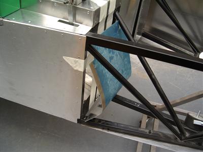
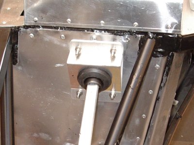
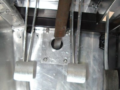 1 - bending the panel to get it into place. 2 - the bushing mounted to the front of the panel. 3 - Inside the footwell, showing the spreader plate.
14th May 2010
Doing various odd bits this week, with a bit of fail mixed in. I bolted up all of the front suspension and got the steering roughly adjusted. It's nice to be bolting stuff together that all just fits for a change. I had to give one of the old sierra hubs a bit of a touch up - I'd kept them in a closed plastic crate in the garage over the winter, one was fine, but one had a couple of rust blooms on it. Didn't seem to have got through the layer of pqr-15, so I don't know if it was just metal filings caught in the paint? Anway, I sanded it back and gave them both a quick respray.
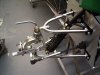
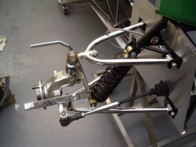 Gratiutous suspension porn. Fwwoooooar!
I haven't torqued it all up yet, because (a) I need a new socket to reach one of the bolts, and (b) some of the bolts will have to come on and off for adjustment once the thing is on its wheels. Steering joints and the top balljoint particularly, so that the toe and camber can be adjusted. I also need to source some new pinch bolts to hold the hubs on properly - I think they're an AF size, need a trip to the motor factors...
Speaking of the top balljoint, there's a gotcha here that I missed, until a friend of camp freddie on the DROC forum happened to mention it to me. There is a spacer, or collar, which goes on the balljoint shaft. This is actually handed, it has a very subtle chamfer on one side which lets it fit snugly against the shoulder of the balljoint:
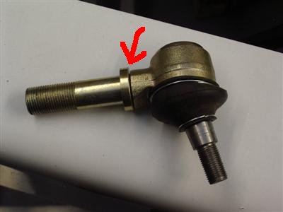
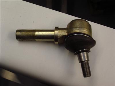 Left - WRONG - there's a gap. Right - CORRECT - the collar fits right up against the shoulder
Easy to miss, so worth mentioning.
I did a bit of painting over bits of the chassis where the powder coat has been chipped by lifting the engine in and out, and around the steering column mounts where I'd been slotting them. Not very interesting, but needed doing. And I've spent several hours turning up some ally covers for the throttle pedal bearing - purely a cosmetic thing. I need to do them before I bolt the pedal box down though. This is where most of the fail has happened, with lathe tools breaking, new ones being ordered and being no good, carrying on anyway and getting nowhere. 3 attempts so far and 3 almost right parts to show for it. Frustrating, because it should be about an hours work for someone competant. But never mind, it's all practice I suppose...
Also been re-routing the brake line around the steering column. I tried just rejigging what was there, but there just isn't enough clearance:
I really don't want to move the t-piece now, because it requires a pretty large hole in the chassis and I want to keep those to a minimum. It's not in an ideal position though, really. So what I'll have to do is rotate it 90 degrees backwards, so that there is no line comming out of the top. I'll have to reroute the other lines a bit, but nothing too major I don't think.
I've actually spent more time this week shopping for things. I'm looking in earnest for a clutch - I'm hoping that an s2000 one is a close enough fit, and that I can just get the flywheel re-drilled to take it. Given the number of replies I had when looking for a gearbox, I thought I'd have no trouble - but so far I've drawn a blank. I guess that nobody tends to reuse old clutches. A new one is hundreds of pounds though, so I'd rather get an old one to play with first. I have managed to pick up a master cylinder off the 'bay though, which was about half the price of all the others I'd seen, so it's a start. Also still looking into engine things, and started looking at which wheels and brakes to get, all of which means more research and reading.
19th May 2010
Still doing odds and sods, which isn't as satisfying as bolting large sections together, but all needs to be done. I rotated the brake T-piece and made up a new "helter-skelter" line to avoid the steering column. There's now plenty of clearance (I think) - I've had a good pull on the column and can't get it to come anywhere near the brake lines (whereas before it was easy to bend it and make it touch), which has to be a good thing.
I also filed the flats onto the steering column. You have to be a bit careful here, to make sure that the steering wheel is going to end up central when the steering is. The steering wheel end of sierra column is triangular, not splined - so you can't just adjust the wheel when you put it on. So you have to make sure that you file the flat on the end of the column in the right place. I found the central point of the steering by marking the input shaft of the steering rack, turning lock to lock (3.5 turns), then turning half of this distance from full lock to find the centre. Very fine adjustments can then be made using the track rod ends.
So that's the column done, for now. However, I know it's all got to come off again for engine fitting, so I haven't bothered bolting it all up properly.
I also finally managed to finish turning up my bearing covers:
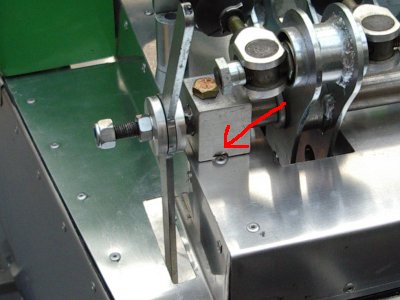
Finishes it off nicely I think, and will help to limit any bending motion of the pedal. The reason they were hard to make was because they are so thin - so machining one side is easy, then you part it off and can't put it back in the cuck to do the other. In the end, I mounted it on a bolt and secured that in a chuck, but it was rather fiddly to set straight. The other thing I had to do was cut a little slot in each of the mounting blocks (arrowed), because I'd foolishly placed rivets in the way. Which meant that I got to use my milling attachment, hurray! But it's another of those "would have saved a couple of hours if I'd thought of it before" moments.
The shopping has continued - I now have a clutch slave cylinder, and a master cylinder, which doesn't fit. Looking at other people's builds using this gearbox (as I should have done before spending any money), it looks as if they have used new master cylinders, rather than donor ones. So I can either adapt it, or stick it back on ebay and buy a new one. I have a possible lead on a clutch, if that doesn't come through I'm probably going to have to bite the bullet and buy a new one.
Engine, again
Still thinking about the engine, a lot. More amateurish tuning discussion follows, don't take this as gospel, it is just my understanding based on reading lots of books and websites.
Looking at the various cams available, they almost all (with the exception of AHMs), have very short duration (260-270) compared to what is generally considered as "fast road" types (270-280). AHMs is apparently 300 degrees of duration, which would point to a cam that is geared for power at high rpm. That would match their 300hp on this engine with standard heads - it would have to be revving its tits off to make that. Most theory I've read points towards a potential loss of mid-low range power in this case, however - the advice always seems to be "if in doubt, go for a lower, rather than higher, duration". All the others seem much the same, by most standards seeming rather mild. That said, the OEM cam's duration is 236 degrees, with even the GTA only having 243 - so 260 is a considerable increase. Bizarrely, the engine in stock form comes alive after 4000rpm, even with such a mild cam...it all seems a bit contradictory to me. On the plus side, a very mild stock cam means larger gains to be made!
Catcams have one of the largest lifts for a "fast road" cam, 11.15mm, which is just on within the "acceptable" range (for wear, which increases with valve lift) quoted by A.Graham Bell and others (He quotes 0.440 inches as being a rough maximum, 11.15 mm is 0.438"). They also state that they deliberately use short durations to maintain midrange power, which makes sense - the question is, how much does that adversely affect top-end power? Most others are in the mid 9s, a couple are in the low 10s. Are they all like this because it's been found that it's best for this engine? Or because companies have just copied other companies? Questions without answers I suspect, unless someones actuall done the measurements.