Rear Suspension
03 June 2009
Moving on to the rear suspension, and the first proper mechanical bits. The diff goes in first, then the de dion bar, then the driveshafts and things.
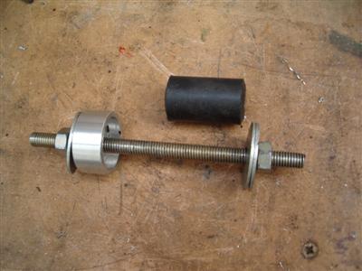
The diff is mounted in rubber bushes pushed into the chassis. These bushes are a very tight fit and so some sort of pressing device is required. Because they are also slightly wider than the holes they press into, the press needs a bit of a cavity at one side. A socket would do the job nicely, however I didn't have one of the right size. So I lept on the opportunity to make something useful with the lathe - mainly for the practice, as I'm sure I could have cobbled something together in about half the time. Anyway, I made a socket out of some ally bar I had, then with a bit of threaded rod, a couple of nuts and washers, and I had a press:
 It may have taken 2 evenings, but it was all useful experience...
Worked a treat, and the bushings went in in about 30 minutes with a drop of washing up liquid:
 Left: in use. Right: 2 of the bushings in place - you can see how they protrude, and why the socket is necessary
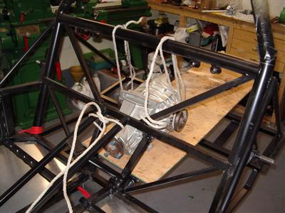
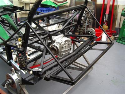
With that done, it was time to hoist the diff into position. Unfortunately, I couldn't get in there with the crane, and with the missus not around, I had to be a bit inventive. A length of ply placed on the rear of the chassis gave me a shelf at nearly the right height; I put the diff on there, then hung it from the chassis with ropes around the drive flanges. Take away the ply and it swung almost perfectly into place, first time as well!
Bolting it in would, you'd think, then be easy, but no...there's a big bag o' nuts and bolts, for the whole rear suspension, and not really much clue as to which goes where. So a lot of trial and error ensued. I managed to get 5 in ok, but the top passenger side one is still confusing me. There is a bigger gap between chassis and diff here, because of the asymetric shape of the diff itself; I have a choice between two sizes of bolt, one is too long, and one is too short. I'll ask on the forum tommorow.
I will also be making up some spacers to fit between the diff and the frame; stacks of shim washers are supplied but I want to do it "properly". So for now, I've only put plain nuts on to hold everything in place, I'll save the proper nyloc nuts until I'm ready to torque everything up for good.
17 June 2009
Well, I got some stainless steel bar (expensive stuff, it seems) and turned up some spacers on the lathe. This took up all my evenings for a week. Would have been quicker but I measured wrongly the first time and had to do it all twice!
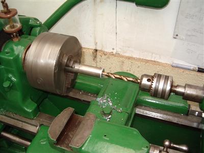
Drilling out the bar, and turning it down to the required diameter. The white stuff is cutting fluid.
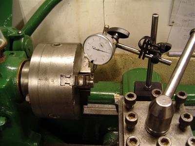
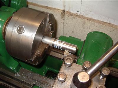
Facing the end. Then once cut to length, the piece is replaced in the chuck the other way around, and centred using a dial gauge, before facing the other end
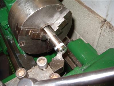
Finshed spacers, and on the right, shown in place. The powered feeds on the lathe make it easy to get a nice smooth finish, even for a beginner like me!
So with that done, it was time to start fitting the rear suspension proper.
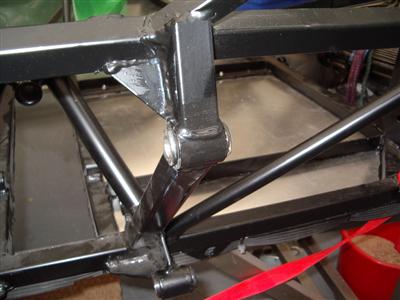
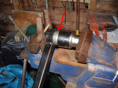
The first thing to fit is the A-Arm from which the main axle beam hangs. This has a spherical bush in either end, which needs pressing in. A fairly large vice is required for this, as it takes a lot of force. Like, hanging your whole body weight on the vice handle type of force. An assistant is also helpful, as it's one of those "three hand" jobs. Thanks to the missus again!
I used the socket I bought for the hub nuts as the press, and a toolmaker's clamp to provide a spacer to allow the bushing to be pushed out of the end of it's housing. The pic below should help explain better - the arrow is pointing at the bushing itself, in between the socket and the housing on the end of the black A-Arm.
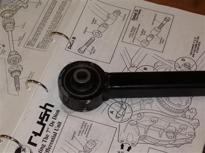
This left the end of the A-arm rather scratched (above), so I gave it a couple of coats of paint (I'm using "Rustoleum" black on the chassis - seems fairly tough) before proceding further. I'm basically touching up everything as I go, as there are myriad little chips and scratches which need covering up.
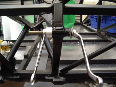
The centre of the arm then bolts onto a right-angled ball joint positioned above the diff. A bit of wiggling to get it in, but fairly straightforwards. The (heavy) axle beam then bolts onto the arm:
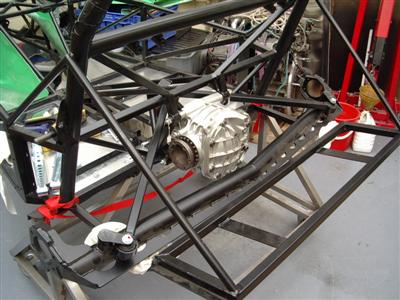
At this point I checked the axle for clearance - the build manual says that you may need to hacksaw 16mm off the differential rear mounting lugs. My axle did just clear the lugs, but I took off about 8mm to be on the safe side. Loads of room now:
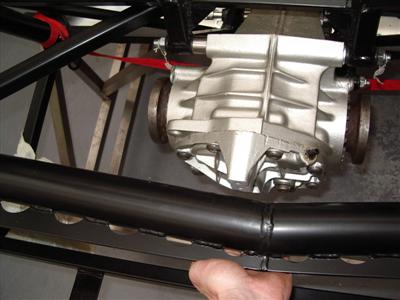
With the diff in place, it is clear that there is no support for the rear of it; in the sierra, these lugs attached to a massive mounting bracket which bolted to the floor of the car. I can see why Pete (WD Pro) on the DROC Forum has added a custom brace to his for added support. His car will be more powerful than mine (cossie turbo nutter!), but I'm wondering whether it's worth doing something similar or not...ultimately it depends if it impinges on boot space I think...will have to have a think.
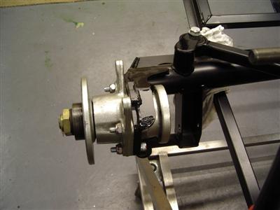
Next job is to put in the rear hubs. These have been sat in my "clean donor parts" box over the winter, and now need the bearings putting in and fitting. (Unlike the fronts, the rears have to be assembled in situ). Fitting the bearings is as per the fronts (see my Reconditioning Page), tap the races in with a hammer, grease up and fit the bearings and oil seals. The hub carriers are then bolted to the axle bar, and the spline axle and hub tapped in from either side. I've nipped the main hub nut up for now, but will require either a bigger torque wrench or some calculations to do up to its specified torque. I've stuck a tag on it for now to remind myself that it needs doing up properly later.
Another trick I've learned from various people is to put a blob of paint on each nut/bolt as you torque it up to its final tightness. That way, you can always see what you've finished and what still needs torquing up. You'll see the blobs of red paint in some of the pictures.
20 June 2009
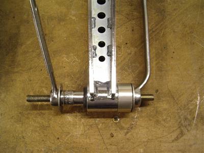
Next was the suspension arms. These again have a bush in each end, which I pressed in as before. After doing a few, I found that it's best to press against only the metal insert, rather than the whole bush. To do this, I used a socket in place of one of the large washers in my pressing tool:
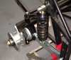
The arms then "just" bolt in. It required a bit of persuasion with the rubber mallet, as they're a tight fit. Then it's on to the coilovers. You take the top spring seat off, slide the spring over the damper, which then bolts into place quite simply. I'm not sure of the torque for the top mounts, I've gone with 100Nm at the mo which is "pretty darn tight", I'll see if anyone has any advice on these. The other thing to note is the adjustment knobs on the dampers; I've put mine in facing the front as I think they'll be pretty much impossible to get at if they're facing rearwards, as the driveshafts will be in the way. Worth mentioning as it would be easy to miss them!
Getting the coilovers in is easy enough; getting the spring seat back in requires that the spring is compressed. And I don't have a spring compressor...so I used a couple of ratchet tie-downs. Now I wouldn't say that this was a particularly good method, as it takes a lot of faffing to get the balance right (otherwise the spring just bends to one side), but it was free!
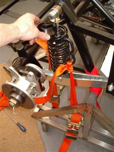
 Left: compressing the springs, and putting the spring seat in place. Right: Spot the missing parts...
So the suspension is now finished, with the exception of the driveshafts. The ones I bought didn't have all of the bolts, and they're nasty torx thngs anyway, so I've ordered some new ones. M8x50 socket heads in 12.9 grade, which isn't interesting until you need to find out what they are!.