
Headstock Rebuild
December 2014
The headstock is a much simpler affair than the apron and gearbox, but rather more critical. I wanted to take the time to get the bearing clearances as close as possible to the quoted values of 0.0007" - 0.001".
I placed the spindle in the headstock to benchmark it (I had done this before dissasembly but best to measure again, just to be sure). It was still a little over, so I again took a little off the bronze bearing shell mating faces by sanding on a flat plate. Take off a little, measure, take off a little more, measure again.


After a few itterations I got it down to just under 1 thou, around 0.022mm (my dial gauge is metric). All running very freely.
The rear was more of a problem as I knew it would be, since the bearing was in a worse condition. I took as much from the mating surfaces as I dared, then as suggested by people on the South Bend forum, started to use shims under the bearing cap to push the bronze shell tighter. I spent a lot of time playing with different shims; under the mating surfaces of the bearing cap as well as under the cap, trying to get the clearance down. The thinnest I had was 2 thou, and that was a little thick to go under the cap - the spindle started to bind slightly. So I thinned it down, again by sanding between two sheets of emery, using a steel block to hold the top sheet, with the bottom on a flat steel plate:
Bit by bit, I got the clearance closer and closer. The final set up used two shims, both approx 1 thou thick having been sanded down from 2 thou stock. One under the rear side of the bearing cap, with the other under the centre of the cap:
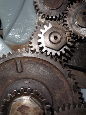
This is a pic just before final assembly - by now I'd added the cone pulley and drive gear to the spindle, these just slide on with no drama.
This left the clearance at around 0.0015" - a bit over, but any tighter than that and it started to bind. The bearing will be not quite round any more (which isn't a bad thing as I understand plain bearings, some "pear-shape" is good for oil flow apparently), and it starts to pinch. Given that it was at around 0.017", it's 10 times better than it was, and as the book says, a bit looser is better than too tight. I'm happy with that.
When I'd been using the lathe, there was a noticable amount of endfloat in the spindle which was noticable when drilling. This is adjusted out using the threaded collar on the rear of the spindle; however, even with that adjusted correctly, there was still perceptible end-to-end play.
This turned out to be the rear bearing sliding in the bearing cap - there is actually clearance between the cap and the bearing shell. 5 thou as it turns out, here shown with a sheet of 0.005 shim stock in the gap:

I presume that this is a manufacturing defect as I can't imagine it's worn away like that. Anyway, an easy enough thing to fix with my ninja-level shimming skills. Two semi-circles of shim stock later, and the endfloat was gone.
The backgear goes in nice and easy; I've greased the gears here, rather than oiling them to reduce splatter, and they don't get much use from me so I reckon that grease will stay on better.

After that, the drivetrain between the spindle and the gearbox is the last thing to go in. This consists of the reverse tumbler assembly, which is a single unit, and the large casting with the sliding gear on.
The gear which meshes with the sliding gear was the one with two missing teeth. I'd hoped to find a replacement, or find someone who could repair it, but didn't really get anywhere. So I thought I'd do it myself, as I had done for the Union Drill.. I used normal Mild steel wire this time as the gear didn't look cast to me, though I am guessing. However there was no pinking as it cooled down so hopefully a good sign. I used a grinding disk in the dremel to get the teeth roughly to shape, then went at it with a needle file. I made up an aluminium template from the good teeth to use as a guide.


Once they looked about right, I mounted the gear and turned it against the sliding gear to see and feel how it was meshing, and just gradually took off a bit here and there until it meshed smoothly with the other gear.

Being honest, it's not quite as good a job as I made on the drill, I don't think. One of them has a bit of a hole at the bottom where the weld wasn't so good, and the tooth between the two repaired ones got a bit "thinned down" as I was filing.
That said, it all works with nary a rumble, and if only part of each tooth is in contact, then that's presumably better than no tooth. It's certainly quieter than it was. Very difficult to do this by hand though, but I don't really have the setup to machine it properly.
Bastarding Rust
At about this time, we had an odd combination of weather, being fairly cold (just above freezing) but at the same time, incredibly humid. For several days, the garage walls and everything it were running with condensation. I've not seen anything like it since I built the garage 6 years or so ago. The first evening I noticed this, I sprayed WD-40 everywhere over the lathe, and oiled everything I could, but the damage had already been done to the exposed parts:


Can't do much about the pulleys really (though in fact they have been covered in oil over the last few years and still worked fine). The backgear shaft was more annoying as I'd just cleaned it and rubbed down with 60 grade oil, so I was surprised that the rust had got to that. Most of the rest was fine, a couple of spots on the ways but nothing major. Not sure what I can do to stop this really, hopefully it'll remain a rare occurrence. I cleaned and painted the backgear shaft so that at least should be safe in future.
Geartrain in
The geartrain and reverse assembly bolt up very easily. The reverse handle had a few big dings in it, particularly the brass section, so I took the time to reshape and polish that up. I wonder why they used brass for just that piece? Would have been good to do all the handles that way, though I guess it would have cost more.


The top end of the geartrain casting is a slot, so that the engagement with the reverse tumbler gear can be adjusted. Nothing in the book about this, so I just did it until it looked, sounded and felt right.
The top gear in the reverse assembly is still held in by that horrible bodged central axle. I've taken the measurements from it, so the plan is to make a replacement when the lathe is up and running again - but of course I'll need the gear to do that, well if I want powered feeds anyway.
Wiring
Something I'd wanted to do for a long while is to fit a reversing switch to make threading easier. I also desperately need to replace the main on/off switch as the "off" bit was rather flaky and didn't always work first time, which is no good at all on a safety-critical part like that.
So I bought a new on/off switch - this one seems to be sold everywhere, by Axminster and several others. Obviously it's not as robust as a proper industrial one, but seems to be considered fine for home use. It has a nice big emergency stop, plus NVR - that's "No Voltage Release", which means that if the power goes off while it's on, it trips to off, so that the lathe won't start up suddenly when the power goes back on. This seemed like A Good Thing.
I found my reversing switch on eBay as per most things. A Dewhurst Drum switch, an vintage thing designed for exactly this job.
The wiring scheme for these is simple enough once you get your head around it, but somewhat baffling at first. I found this Instructables article to be invaluable here. I've reproduced the diagrams here:


My motor didn't have the Z, AZ, A, T terminals, they were all numbered, but I was able to work out which was which with the help of the note left by the installer. Same design, just different labelling. In the image above, Z and T are the starter coils, and it's these that need to be reversed to make the motor run forwards or backwards. They are connected to terminals 2 and 6 on the drum switch, which are the switchable ones. AZ and A are constantly connected to live and neutral respectively.
The start/stop switch came with it's own wiring diagram, but did need some crimp on ring terminals which weren't supplied - the Dewhurst needs these as well.
I didn't get many photos of all of this unfortunately. One thing I did find was that the drum switch didn't work at first. The contacts are just springy brass fingers and they'd become bent over time. Simply bending them back inwards slightly restored the contact with the central turney bit of the switch and it all worked fine.
So then I needed to mount the whole affair. I needed to make up a mounting plate, for which I used a sheet of 3mm steel, drilled and painted, and bolted onto the existing support. Quite neat I think, and everything's nicely to hand.

 I must clean that bit of wall!
Even better, it all worked the first time I turned it on, which was nice! I'd read a couple of comments regarding the drum switches, saying that they weren't really suitable for switching the lathe on and off with, just for setting the direction. That is, you should turn it off with the main switch, then turn the drum switch, then turn it back on.
I did a quick test with the drum cover off and the power on, just to see how true this was. I can report that it does indeed spark and arc like a bitch if you throw the drum switch when it's powered up, all rather like Frankenstein's basement. So yes, it's most definately best to turn off the power before moving the drum switch.
After all this, I have to say that the lathe runs soooo much quieter than it did before. I'm sure the headstock clearances have a part to play in that, particularly the endplay, and the repaired gear no longer rattles so much. It all feels much tighter, in a good way.
So that's the headstock all done - I'm getting close. What I still do need to do is to sort out the drip oilers for the main bearings. I'd hoped to "just" buy new ones, but of course it's never that simple.

I had a bit of a 'mare working out what thread the existing ones had. They're about 0.510" (or exactly 13mm) by 19tpi. This turns out to be a 1/4 inch British Standard Pipe fitting, but what threw me for a long time was the fact that the 1/4" in "1/4 bsp" does not refer to the size of the thread, but the size of the pipe which would go in such a fitting. So for ages I was looking for half inch screw threads and wondering why none of them were 19tpi...D'oh.
Anyway, oilers with such fittings seem rare, most of the ones seem to be 1/8bsp. So I'll probably get a couple of adapters - I was thinking of turning some up, but you can buy them for about 3 quid apiece and I probably can't even buy the brass stock for that price. I've considered refurbing the old ones but they are in such bad shape I'm not sure I'd be able to.
February 2015
Work on the lathe has been a bit sparse of late due to the curse of DIY, but I've been getting the odd bit done and she's getting close.
Oilers turned out to be easy in the end, two in 1/8 bsp size, which is what Myford use and hence are readily available, and two 1/4bsp to 1/8bsp adaptors, all screws together nicely.


They're somewhat smaller than the old ones, but since I'm not running it for 8 hours a day, smaller ones are probably better. Cheaper, less mess and oil loss if I forget to turn them off, and less likely to get knocked about.

And with that, the headstock was complete. Just the tailstock, crossslide and compound to do now.