Throttle
19th April 2011
Now that I have most of my engine parts back again, there are a new set of jobs I can get on with. The main one of these is fixing the pedal box, and getting the brake lines finished.
The reason I couldn't fix it was that I needed the throttle body to work out how much cable pull I needed, so that I could drill the hole in the accelerator pedal - since the whole pedal box assembly has to be removed to get that pedal out, it made no sense to fit it until the pedal was done.
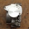
Firstly, I had to reassemble the throttle body, which I'd dismantled nearly 2 years ago when I was trying to work out how to fit it in. That done, I needed a cable to see how it would all work together. A quick trip to my local bike shop furnished me with an MTB brake cable, which will be plenty strong enough. In addition, I have the tools to cut and crimp these, whereas anything larger and I'd have to get it specially made.
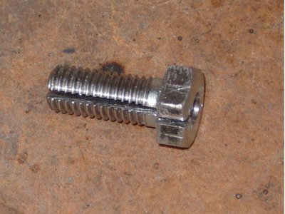
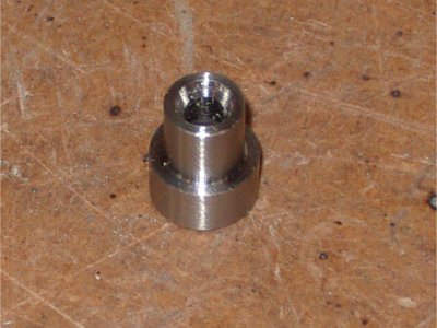
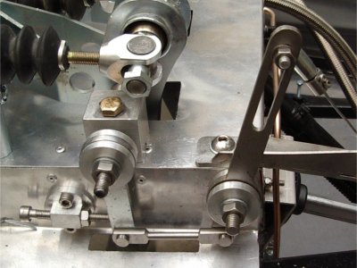
In order to fit it, I needed to make adaptors for the ends (which are designed for much larger automotive cables). Lathe to the rescue! On the throttle side, I drilled out an M12 bolt, and bored out one end larger to fit the cable outer in. Then I cut a slit along its length (using two hacksaw blades side by side, as suggested in the build manual), so that the cable could go in. This then bolts onto the standard throttle cable bracket:
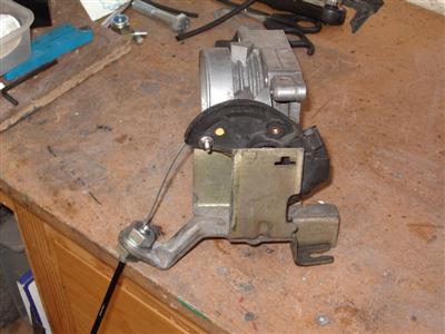
The standard bracket is a huge heavy thing, and has attachements for other cables (the automatic kickdown cable I believe), so I'm going to cut away the extraneous bits.
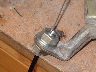
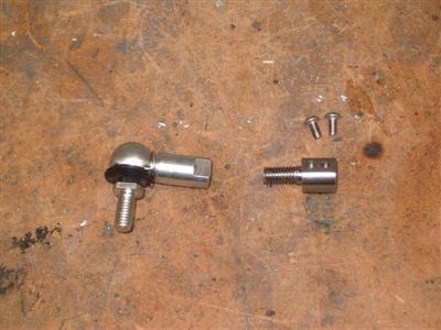
At the other end, the hole on the dax-supplied bracket was much smaller, so I turned up a simple ferrule from a bit of stainless:
With that all done, I could see how much cable pull I needed, and hence where to drill the hole in the throttle pedal.
But Oh Dear.
The throttle needs 60mm of pull; the Dax pedal only gives me about 45. If I removed the stops I think I could just about get it to give the required pull, but you'd have to move the pedal about 15cm - it'd be like driving an old bus.
So, something will have to change. Given that, I've gone back to basics - work out how much pedal travel I would like, and I'll make it work with that.
The travel in my road car is nice, and measures at 75mm. With this as a baseline, me sitting in the car and my Glamourous Assistant marking where the end of the pedal moved, we worked out where the pedal should be at rest, and how far it should move. So far, so good.
The options for getting the pull I need seem to be: either build a linkage at the pedal end which increases the amount of pull, or reduce the size of the lever on the throttle end. Currently I'm favouring option 2, as it is simpler; my only concern is that the cable on the standard throttle goes over a cam, which changes the ratio of pull to throttle opening as it opens. If I make something, it will be simpler and with a constant ratio; so might make the throttle a bit sensetive. One to sleep on, I think.
Prototyping
5th May 2011
Over the last couple of weeks I've made up a prototype system for the throttle, which has been pretty labour-intensive, but for something like this, you can only really tell if it feels right once it's made, so it's the only way really. Measurements give you a starting point but that's all.
In contrast to my original opinion, I came to the conclusion that making a new linkage would be a good thing, because I could make it adjustable. Since I won't be able to change the travel on the brake pedal, being able to adjust the accelerator will be useful to get the relative positions right.
The first thing I did was add an adjustable top stop to the throttle pedal so that I could set its rest position. I'll use a rubber bumper for the end stop as it has to take much more force. This was the first actual piece I've made with my lathe's milling attachment, and I was quite stupidly pleased with myself despite its simplicity!
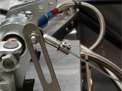
With that in place I could start measuring the movement and space I had to play with. After much messing around with cardboard cut-outs, what I've ended up doing is adding a pushrod from the throttle pedal, which pushes on a new lever with a fairly massive leverage ratio. This is slotted to allow the cable attachment to be moved to adjust the amount of pull:
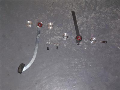
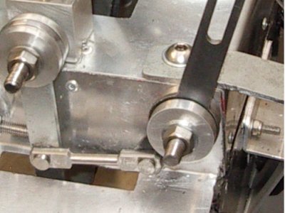
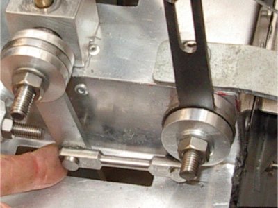
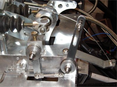 LH Image shows the parts of the linkage, before the lever was slotted. RH image shows it all in place
All the various linking rods and pivot pins were turned up on the lathe out of stainless bar. The lever has a skateboard bearing in as per the throttle pedal, with another pair of ally bearing caps to hold it in place. I also chopped the top off the throttle pedal as I wouldn't be using that.
So this worked, basically. But even then I still could only just get enough cable pull, and the pedal travel still feels a bit long for my taste. So a new (smaller) pully on the throttle is needed anyway. (My thanks to the reader who pointed me in the direction of the Alfa 75 throttle, which has a smaller cam - I've not managed to find one alas, but it's useful all the same.)
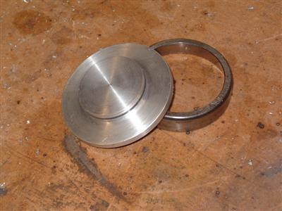
So I knocked up a simple pully and bodged it onto the throttle (I was well into "it's only a prototype" mode by now :-) ) to see how that would be:
 LH - Simple round pully. RH - section cut out to hold the cable end
 All in place
Then it was "just" a case of tweaking the angle of the cable holder to match, and playing with various positions, trying the lever different ways around, etc, to see how it all felt. In short, it gives plenty of adjustability, and I can get a nice short travel pedal. The downside is that it's a rather heavy pedal - the small throttle pully and short pedal travel make this rather inevitable. There are a couple of things I can do to mitigate it though - firstly, the cable I'm using is still about 3 times as long as it will be - but I don't want to cut it down until I have the engine in and know the throttle's exact position. But that will definately help, as there is always a lot of friction in the cable outer.
Secondly, the angle between the pushrod and bottom of the pully is not giving me the best mechanical advantage throughout its range of motion:
A straight lever and longer pushrod will help there.
I expect that it will still be a bit heavy, and I need a return spring on the lever as well - so I will probably put a helper spring on the pedal to ease it a bit.
So with all that in mind, I need to remake a few bits - the pushrod, the lever, and the pully. I've ordered a bigger chunk of ally bar for the latter so that I can machine it to incorporate a mounting plate. I'm still not sure if it'll be ok being plain round, or too "touchy"; I might mount it eccentrically to somewhat replicate the action of the standard cam. The lever used up my last decent sized bit of 3mm steel plate, so I've ordered some 4mm stainless, which will be better anyway. I will also probably remake the cable holder on the throttle so that it is somewhat lighter, and make it rear-exit as that will help with the cable routing. Another thing is the attachment of the cable to the lever - I was at the Stoneleigh show at the weekend and noticed that a lot of people have used a ball joint and cable adjuster, which looks a lot neater and more convenient than my homemade clamp.
The ironic thing with all of the above is that I could have easily bought all of this stuff at Stoneleigh and saved on the postage, but I finished it all just a couple of days too late.
Other Stuff
12th May 2011
Been a bit frustrated over the last week - various bits I've ordered to make the throttle were sent wrongly (ally instead of stainless, that sort of thing), it's all been sorted without much trouble but it's stopped me getting on with things. The folks doing the flywheel aren't making much (any) progress either, I hate chasing people up but it seems you have to to get anything done.
So, no throttle, but I thought I'd make up the brake lines to the master cylinders. You may remember that I'd been advised to put a join in, rather than run a single line from the callipers to the cylinders, so that the bit you see doesn't get mangled while it's sat there for a year or so. Turns out to be good advice - gawd knows what state the lines would be in given the number of times I've had the pedal box on and off.
Quite pleased with these, hardly any kinks:
I couldn't quite finish them though, because I ran out of the little plastic clips - need to buy some more.
Then I finally got fed up with taking the bonnet off and leaving it on the floor, and made up some bonnet stays. I've used 2mm wire rope, a couple of carrabina clips, some heat shrink, and a couple of large Mikalor clips I had lying around. The ends of the rope are doubled over to form a loop, and heat shrink holds it all together - nice and neat and seems plenty strong enough:
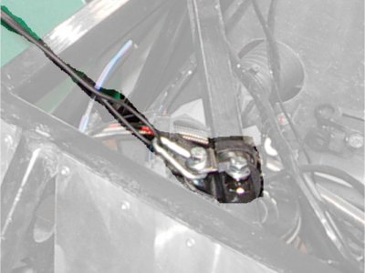
The clips mean that it's easy to disconnect if I need to take the bonnet off completely. I may need a solid stay as well if I want to leave it up outdoors, but it's a great help just being able to open it and work underneath. Should have done it ages ago, really...
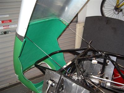
I then had a bash at fitting the side panels. I'd always intended to leave this until I got the exhaust fitted, but I had a close look at some Rushes at Stoneleigh, so I've a better idea of how it all fits now. Some people have them virtually flush to the sides, others have a very large gap of 3-4 inches or so; I liked the look of 1 1/2" or there abouts, so figured I'd go for that and get the exhaust made to fit around it.
Nothing too complicated here - quite a lot of trimming and bending to get a nice fit with the scuttle, which is an area where you often get poor joins in my opinion. Then, just a few M5 rivnuts to hold it in place, and...bugger. Stripped all the threads off of my (cheapo) rivnut tool (and knackered the rivnut into the bargain). So my progress there was also frustrated as I need to buy a new tool - and spend a half hour drilling out the offending rivnut, which is an absolute PITA.
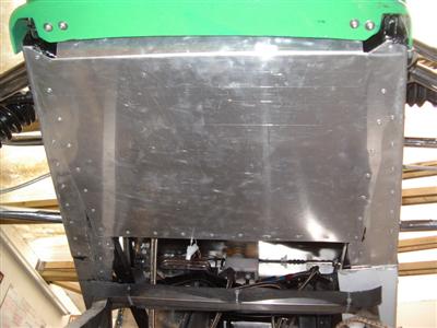
So from there I moved on to pannelling in the underside of the nose. I'm planning to panel out as much of the floor of the car as is reasonably practical - to start with, this is the very front, and under the rear tub, with perhaps bits around the engine bay and transmission tunnel later. I've no idea how much difference it'll make, but the tub looks like it will cause a huuuuge amount of drag. So I don't think it can hurt, apart from the addition of a Kg or two. At the front, who knows - it just looked "wrong" having the GRP nosecone and nothing behind it. A floor panel might at least help duct the air through the radiator rather than downwards in front of itf.
Anyway, this was a simple enough job - 1.2mm ally sheet, wurthed and rivetted as usual. Almost harder to get a meaningful picture of, than to do:
It must be said that with this, my custom side panels around the suspension, and the flared sides, the small infil panels that you rivet on right back at the begining of it all are completely redundant - if I'd have known back then, I wouldn't have bothered with them at all.
So now I have about 4 or 5 half finished jobs, all waiting for various things to come through the post. The throttle is the main one though, so I will be pressing on with that as soon as I can.
Throttle (Finally, this time)
27th May 2011
When my various materials arrived, I got straight on with making up the throttle linkage. First up was a new longer pushrod and lever. These were much the same as the first ones, so pretty easy now I new what I was doing. The mechanical advantage on the lever is now much better, plus it's made of shiny stainless:
I also picked up a balljoint and turned up a cable connector to match. This is just a threaded bar with a hole through, and two M3 bolts to clamp the cable. The hole means that I can move the cable a couple of cm either way, to get fine adjustment. Much better than the old one:
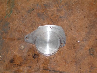
Then it was on to the pulley. I actually made two, as it turned out. The first one I made up with the pully itself mounted off-centre to give an eccentric action similar to the original cam. I offset it proportionally by the same amount. And this worked really well - the pedal action felt immediately much, much better, far less stiff. But it was still using the standard cable holder, and pulling from the front - really, I wanted it to pull from the rear, because I'll get much better cable routing. I'd hoped that I could just turn it around by 90 degrees, and remount it, but that was not to be because of the mounting holes. So I had to make another.
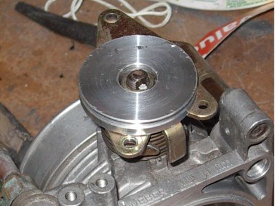
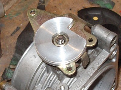
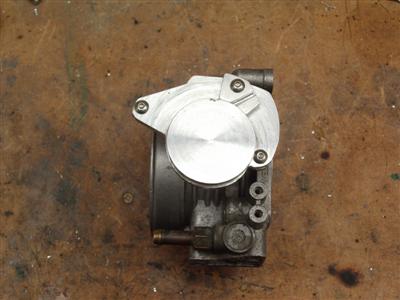
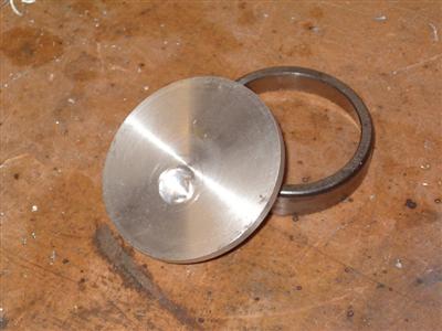 Left - front face of the pully. Notice that it's aligned centrally with the backplate. Right - rear side. The off-centre hole is where the throttle spindle sits, so that the pully itself has an eccentric action as it turns.
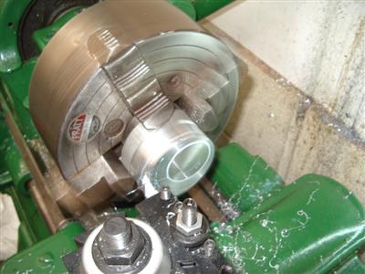
Since I now knew that it was going to work, making the third one didn't seem like too much of a chore. What I needed to do was turn it so that the pully part was off-centre to the back-plate part. To do this, you mount the whole thing off-centre in the lathe's 4-jaw chuck, and turn away as normal. It was the first time I'd tried this, and whilst it looks a bit weird spinning round, it was simple enough. The hard part was working out how much offset to use. Hopefully you can see it in the pic:
On the subject of turning and lathes, as a brief aside, up until now I'd been using carbide insert tooling. I'd read a lot of people saying that DIY-ground HSS was the way forwards, the idea of making up my own tools seemed a bit daunting, with loads of diagrams of angles and things. Plus, HSS blanks are not cheap. However, having now got a bit of experience and seeing how the carbide ones work and how they're shaped, I thought I'd give it a go, and bought some HSS blanks at stoneleigh. A couple of videos on youtube, particularly tubalcain's how-to videos and an original Southbend instructional movie from the 1940's helped me on my way. Turns out it's really not hard at all. Plus where I need a specific shaped tool for a particular job, I can just grind one up - which has already proved useful. So I'm now an HSS convert - anyone want to buy a load of carbide tooling?
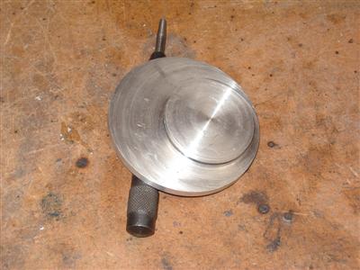
So anyway, this pully has the pully bit offcentre, and the spindle hole in the centre. I then drilled holes to mount it to the existing alfa backplate, and cut away the bits that weren't required. Finally, I made up a clamp to hold the cable, which just bolts on:
Now we're getting somewhere!
The last job was to make up a new rearwards-facing cable bracket to replace the old heavy one. A bit of 2mm stainless did the job there. Initial tests showed a bit of flex in both this bracket and the dax-supplied one at the throttle end, so I welded a strengthening gusset to each. I say welded, it was more "wave the torch around and splatter hot metal roughly in the right place". Seriously, I haven't done any for a bit, but I seem to have lost the knack of doing a vaguely neat weld - these are structurally fine, but look awful. Never mind. They stopped the flex, anyway
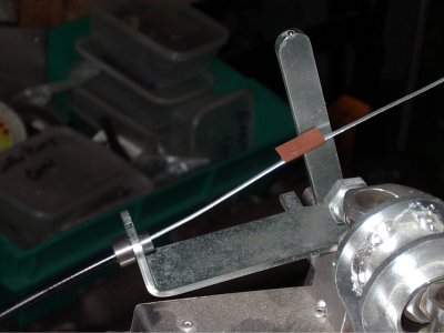
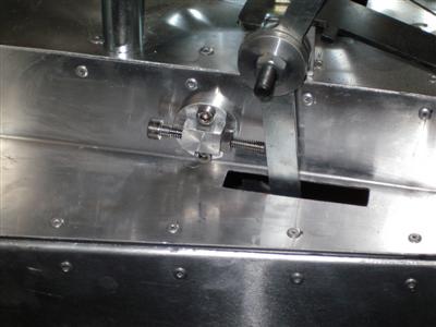
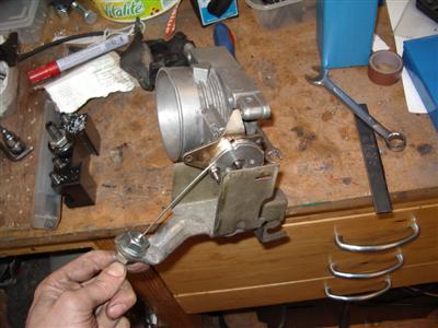
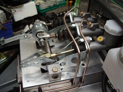
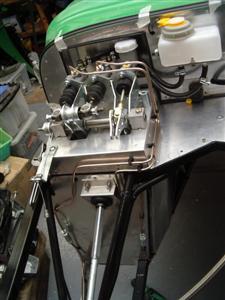
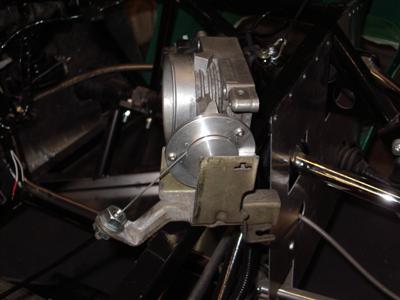
So that all worked and felt right at the pedal end. I can adjust the pedal travel from just under 5cm to, well, way more than I'd want. You can see all of the various bits in the image below; since the engine isn't in, I just clamped the throttle body to the chassis so that I could check the movements:
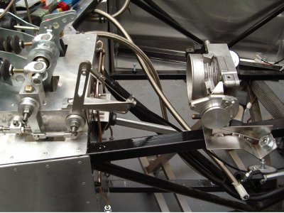
I'm not goint to get my hopes up too much, but it seems possible that the rear-mount bracket might mean that I don't have the problem with the throttle fouling the clutch pedal. Which would be an exceptionally good thing.
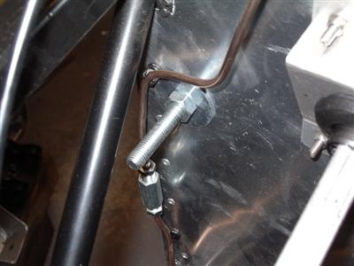
Last, but not least, I wanted to put in a pedal stop - I don't really want the full force of my foot going onto the stop on the throttle itself. And again, I wanted it to be adjustable so that I can, well, adjust it. Toyed with a few ideas and eventually settled on an M10 bolt with a big washer welded onto the end. Another washer with a nut welded to it and bonded to the footwell panel to mount it, and on the other side of the panel, another big washer and nut to lock it all up. For once, a job which only took an hour or so to do! Simple, and does the job rather well. So I can adjust pedal position and travel, which should mean that I can get everything set up just how I like it.
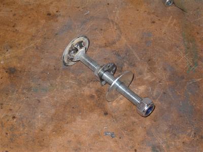
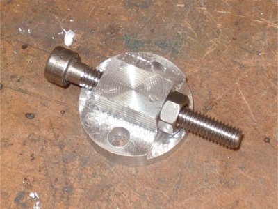
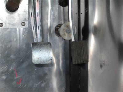 Left - the various parts. The cut down washer/bolt is bonded to the inside of the footwell panel. Right - view from inside the footwell. Below: View from the engine bay. To adjust, the nut is loosened, and the bolt simply screwed in or out.
Other bits
All of the above work had been stopping me bolting down the pedal box, for about a year. So it felt good to get that finally done. It took a surprisingly long time, largely because it's now quite hard to get at the bolts inside the car, and it's quite fiddy bolting up the master cylinders. But all done now, another bit completed.
Other news is more rageful. There's still no progress on my flywheel, which I'm pretty annoyed about, but there's little I can do except keep on at them. The downside of having work done 150 miles away I suppose.
So the next job will be to get on with the side panels and rear undertray.