Tailstock, Compound and Cross-slide Rebuild
February 2015
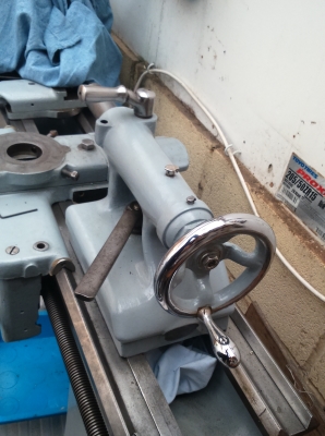
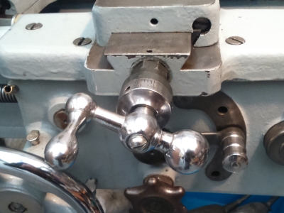
Finally, my handles returned from the rechromers. For some reason I didn't take a picture of them all, which was dumb, but I had the large main apron handwheel, the tailstock handwheel, and the crosslide/compound knobs all chromed and polised. Very pleased with the results, (and the price - only 70 quid for all for), though less so with the 10 weeks it took for them to be done.
Given the rusty climate I live in, I think if I was starting again I'd get all of the handles with knobs on done - the only reason I didn't really was that many of them are irreversibly fixed onto handles or larger assemblies. But actually, I wouldn't hurt to chrome the lot and paint over the supporting parts. So yeah, I'd definately advise it. The crosslide / compound handles in particular were frankly knackered, and are now new and shiny - even better they'll now stay that way.
The new crosslide screw I had made requires a threaded hole screwing in the end (newer lathes had a male thread on the end, mine needs a female), for which I needed the tailstock, so that was the bit I attacked first. In fact, all of the next bits happened in a bit of a jumble, I've broken it into sections to make it easier to follow, but some of the pictures may look out-of-sequence for that reason. At various points I needed to use the crosslide for example, so I had to put it together temporarily with the old parts.
Tailstock
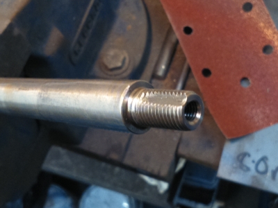
The main things needing attention here was the taper inside the quill, and the screw thread on the main drive screw where I'd had to hack the old fixing bolt off. The latter just needed a quick clean up with a die, as I'd managed not to damage the thread during my butchery. It's a bit corroded and tired, but good enough that cleaning it up seemed a better option than recutting it smaller.
The inside of the quill was badly scored. In use, things generally fitted into it ok, but it wasn't unknown for a drill chuck to spin. So I bought a new MT3 reamer to clean it up.
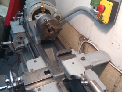
Having tried for a while to ream it by hand, and making very little impression (it's very hard to apply enough downward pressure), I figured that I'd mount the quill in the tailstock and the reamer in the lathe, and use the tailstock to apply the pressure.
First off, I needed to align the tailstock, which I did in the normal way by mounting a centre in the headstock and one in the tailstock. This needs to be done with the ram fully in and fully extended, to check for any tilt up or down. Adjustment is by shims under the body of the tailstock. As luck would have it, I refitted the shims I'd used previously and it was immediately spot on.

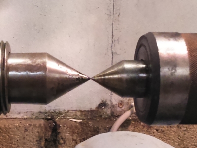 Happy with that. But bloody rust, everywhere. Those centres have been in a sealed crate with dessicants and covered with spray oil :(
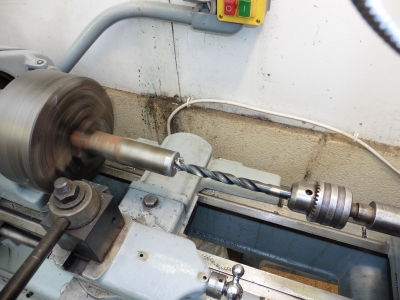
So I mounted up the reamer and off I went
 DO NOT do this!!!
Well this is almost the right way to do it, but running the reamer under power (even slowly) is a good way to jam things up. This is rather a violent thing when it happens. Happily the drive belt slipped, rather than anything breaking. I've become a bit of a fan of belt slippage over the years, it's never slipped while cutting, but it's saved me a couple of times when things have jammed. In a production environment I guess you'd need to tighten the belt a bit to get the maximum cutting depths and speeds, but I reckon I'll leave it just where it is.
Anyway, slightly shocked by that, I managed to extract the reamer (which involved dismantling the tailstock so that I could drift it out), and went online to see how to do it properly.
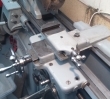
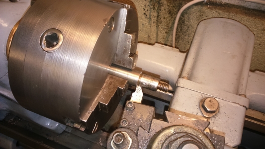
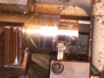
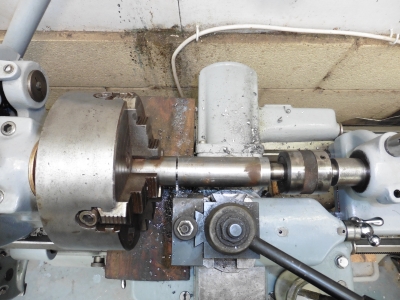
The generally accepted way it seems, is to mount a centre in the headstock, this goes into the centre hole in the tang of the reamer. The tailstock wheel is used to put pressure on the reamer, and it's turned by hand using a spanner. Not, repeat not, under power.
 This is the correct (safe) way.
Quite hard going, but about a half hour of turning was showing cutting along the whole length of the reamer. In my mind I'd imagined that I could cut all of the scoring out, but the reamer is really only a finishing tool and takes of a few thou. So the quill still has some deep scores in it, but as a few forum posts have pointed out, they aren't really the problem. It's raised burrs which stop the male taper seating properly, depressions don't make a lot of difference. What the reamer does, is take all of the raised edges off, and ensure that the flat bits have the correct taper. So although the quill still looks a bit battle-scarred, it's noticably better at gripping tapers now. If I push one in and give it a small twist, it now needs both hands and a fair effort to remove, just as it should do.
So I think I will consider that done. To clean it up more would require reboring with a single point tool, then re-reaming. The compound doesn't have enough travel to cut a taper that length, so it'd need a taper attachment to do properly. I don't want to risk messing it up for what would really only be a cosmetic improvement.
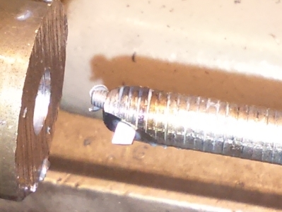
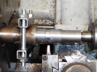
I also needed to polish up the locking handle as I'd done for the rest. Then I reassembled, and checked the action. There was much less backlash than before, but still rather too much. The reason was that there was a fairly large amount of endfloat (17-18 thou); this was because the shoulder that the handwheel screws down onto was protruding too far beyond the face of the tailstock. It's arrowed below, a bit hard to see because 18 thou isn't much:

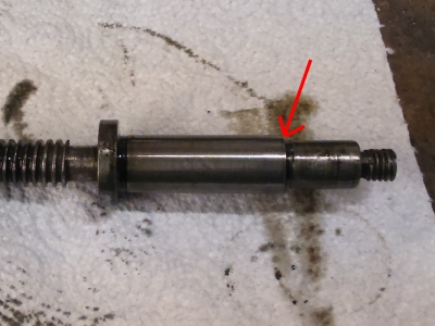
This will just be due to wear on the mating faces, which will take quite a load when drilling etc. Simple fix - take 16 thou off the shoulder. Before doing this I rebuilt the 3-jaw chuck, but I've gone into that below.
Very simple, and has made a massive difference. There is still some backlash because of wear in the acme screw, but it's vastly, vastly reduced.
So that's the tailstock pretty much done; the last thing was to replace a missing oil cup in the top.
3 Jaw Chuck
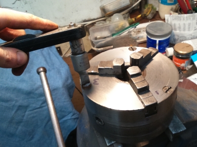
I had a bit of trouble at one point getting the 3-jaw to run true. After some faffing, I found that some swarf was preventing it seat properly on the spindle. However, seeing how much cack there was inside it, and given the generally battered appearance of it, I thought I'd take it apart and clean it. It's always worked pretty well so I don't think there's anything majorly wrong with it, but it was rusty as hell when I got it, and it's had 5 years of use since then. While I was there, I also planned to give it a surgace skim in the lathe to clean the body up a bit. Complete vanity but I get envy every time I see a picture of someone's lathe with a nice, shiny chuck on it.Taking it apart wasn't too hard - 3 large cheese headed screws hold the chuck to the backplate. This required the drop link socket again - honestly I could not have done any of this without that one tool. Notice also that I've marked each jaw - they are stamped as well.
I unfortunately did need to drive a screwdriver into the gap to force the backplate off - there's nothing really to get any purchase on, and it was tight. Always seems rather messy, but I tried for a while and really couldn't see another way.
With the backplate off, three allen bolts are revealed which hold the chuck body together. Out these came, and again I needed to use a screwdriver to pop the two sections apart.

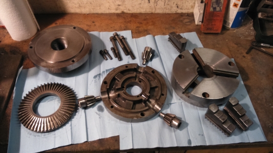
This reveals the three drive gears, and the main gear which has the scroll on the other side that drives the jaws in and out.

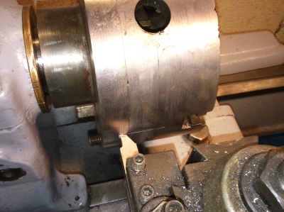
So that all had a "darn good cleaning". I then reassembled the chuck body and faceplate without any of the parts in, mounted it in the lathe, and took something like 15 thou off the sides and face. Just as little as a I could to make it look presentable.

A couple of things I found here. Because there are gaps in the body for the jaws and things, you get an intermittent cut. This blunted an HSS bit in very short time, and left gouges. So I switched to one of the small carbide bits I have, which seemed entirely unaffected by the whole thing and left a nice clean finish.
This of course removed all of the stampings for which jaw was which etc, so I redid all of those - I made sure I marked everything up in places I wasn't going to be machining first!. Then scribed a line with an HSS bit so that everything can be kept in the same orientation upon reassembly:
And back together we go:

Cross-slide/Compound fitting
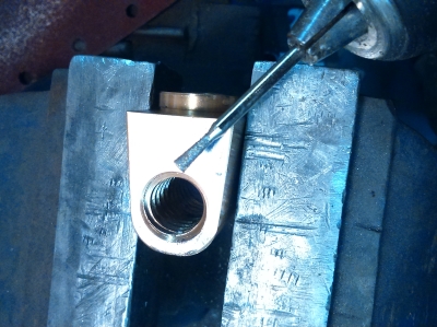
I found I had a few modifications to make to the new screws I'd ordered - the handle ends both needed keyways cutting as the handles both have a small dowel inside, and the compound needed and internal hole cutting and threading, because the original external nut was long since lost, and in fact had never been on there since I'd had it. So I planned to replace it with a slot-head screw.
Simple enough stuff - drilling and threading was easy with my nice new tailstock. For the keyway, since I didn't have a toolpost grinding attachment, or a slotting saw for the lathe, I just cut them by hand with a small grinding disk (a dremel one, but my dremel needs a new collet chuck, so I just used an ordinary drill). A bit at a time, gently does it. Real machinists may look away now...
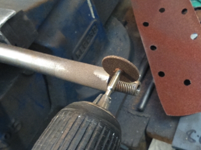
I could probably have mounted the screw in the toolpost and done it that way, maybe, but it really didn't seem worth the effort.
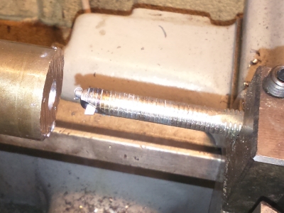
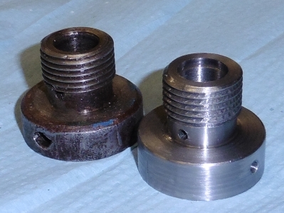
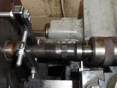
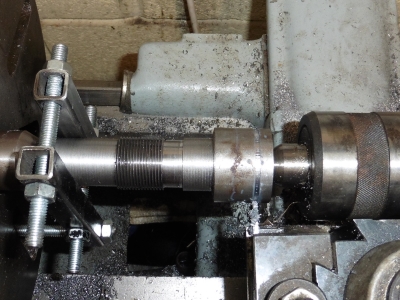
The compound fitted with no other issues, the cross-slide was a bit more problematic. I was going to try and put some thrust bearings in, as I'd seen in a large-dial conversion, but that was on a heavy 10. I couldn't find any bearings to fit the screw shaft of the 13", those with an appropriate ID had an oversized OD. I did buy some and try to slim them down, but it just wasn't practical. So in the end I shelved that idea, you'd have to make your own races and source some smaller balls separately I think. Aside from that, when I assembled it I found that it kept binding. This was quite hard to trace but eventually found that it was due to slight differences in the lengths of the gear cuts. Easy to see below, old screw on the left, new one on the right:
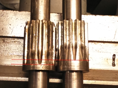
Although most of the gear contact was at the front, the cuts were just a bit short and causing them to bind slightly. After a great deal of marking, refitting, and stripping, I was happy that all I really needed to do was open out a bit of clearance at the tapered ends of the cuts a touch, rather than having to get them all properly recut much longer. So I was able to do that with the grinding disc again:
Apparently, hand cutting gears is getting to be "my thing". It really wasn't much here though, as I say just opening out the tops of those tapers rather than the actual meshing parts.
So that did the job nicely. Then I noticed that the new crosslide nut didn't have an oil hole in. You're supposed to oil the crosslide periodically by removing the bolt which goes into the brass nut, and putting oil in there. The nut should have a hole in to let the oil onto the screw. So I drilled that:
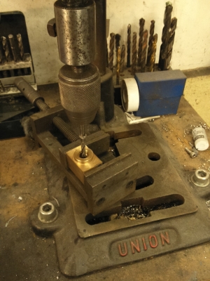
This of course leaves burs where it breaks through, which stick into the thread. I removed them with an upside-down tapered grinding bit from our bit box o' dremmel attachments. The reverse taper lets you chamfer the inside edge of the hole:
Nearly there. Yet another reassembly found that it was binding at a certain point. The old one had, too, and I'd put it down to something being slightly bent. However, when I looked, I could see that it was due to a raised part of the cast lathe body was blocking the brass nut. Not by much, so I simply ground the outside of the nut down a bit until it no longer caught. This has the rather nice effect of letting the cross-slide go much further, until the toolpost is dead central with the spindle:
This is something which had always been a bit of a problem when using the milling attachment - it was always hard to get things central with the cutter as I didn't have quite enough cross-slide travel. So that's a problem fixed.
So finally, it all went together and fitted. The last thing to do was to carefully drill the hole for the grub screw which holds the dial in place. The position of the dial actually controls endfloat (and hence backlash) for the whole screw, which frankly is a crap design, but anyway. But this means that the screw hole needs to be done very carefully.
I was a bit nervous about it, but figured that the best way was to use the hole in the dial as a guide, with everything put together. I ran a tiny flat-ended grinding bit down there first, to give a bit of a flat on the round shaft so that the drill bit wouldn't skate off everywhere, then simply drilled it in place, while keeping the dial clamped. And it worked perfectly. To my utter joy, there is now zero perceptible backlash. I know that zero isn't possible, but it really is so tiny I can't see it. Compared to the turn-and-a-half I had before, this is amazing. The downside is that the new screw and nut are really rather stiff, some oil helped a lot, and they will losen up a bit with use. Very pleased with that.
Pic of it all together:
Apparently I need to touch up the paint! Poor thing is getting dirty and chipped before I've even had time to do the "glamour shots". Regarding the dials, the cross-slide one is not too bad, the compound one is pretty tatty. But I can't find anyone anywhere who can make or engrave new ones, so I think I'm stuck. I've just cleaned and polished, which is about all I can do. At least the handle won't rust anymore.
Self Replicating Machine
So now onto the very final part of the rebuild. I am going to make 2 replacement parts, for which I must use the lathe itself. These are the bushings for the compound and cross-slide screw
These will involve boring and threading and all sorts of things I've never really done much of, so should be an interested experience in itself. But the lathe is already the best it's been since I've owned it, tighter and less rattly in every way, plus I have a reversing switch now, so I think I'm ready.
Compound Bushing
10 April 2015
This is a simple enough part in concept, but represented a number of firsts for me: First threaded part, first accurately bored part, and with the highest requirements of accuracy and concentricity of anything I'd yet done. And true to form, I didn't get it right first time. The first one was good, perhaps a half a thou too large in the bore, but otherwise spot on. Except that I cut the thread left-handed, which I didn't realise until I came to screw it into place. N00b error.
For the booring, I didn't have anything small enough; I have a carbide boring bar but it is far too large. So as mentioned in a number of books and online posts, I made one from an m10 bolt (would have preferred a bit of plain bar but I didn't have anything to hand). This is cross-drilled near the end to take a bit of broken drill shank, ground to a cutting edge. In my old copy of "The Amateur's Lathe" it mentions that drill shanks are softened and need hardening; I don't know if this is the case these days, but just in case I heated it to orange heat and quenched it.
A hole drilled lengthways from the end is tapped to M3 and allows a grub screw to tighten down onto the drill shank to hold it in place.
This worked pretty well; the tip did need stoning fairly regularly to keep it keen but I suspect that this is a function of its small size. I kept cuts small, a few thou at a time only. Towards the end I was able to take a half-thou off at a time until the compound screw was a very close running fit. I didn't actually bore it to the final size to begin with; I got it to within a few thou, then shaped the outside and threaded it, so that I could trial fit the bushing into the compound. This let me determine where the oil hole needed to go, which breaks into the central bore. Drilling this leaves a burr on the inside of the bore, so doing it before taking the bore out to its final size is wise, as then the burr is removed during the final cuts.
Roughing out the outside was straightforwards enough. For the threaded section, a small gutter had to be cut from the shoulder - it's impossible to thread right up to the shoulder because it gets in the way of the 60 degree tip. So the gutter is cut down to the minor diameter of the thread, wide enough to give clearance.
 Cutting the gutter, using a flat-ended tool
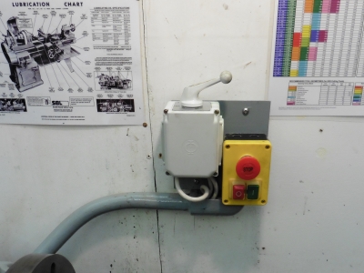
The threading itself was the first time I got to use my reversing switch in anger. It gave me a few issues, blowing the 13A fuse in the switch again and again. In fact it happened a few times before I tracked it down to the switch; at first I thought I must have wired the motor wrongly. But what it was,was arcing in the switch because of poor contacts. (Note, I was not turning the switch with the power on, I was turning off with the main stop switch, then moving the reversing switch, then turning on again). A bit of bending of the contacts improved it somewhat, but it still happened, albiet less regularly. I was on the verge of writing the whole thing off and buying a new one, when in a last ditch attempt I bought some dialectric contact grease; a good blob of that on each contact seems to have cured it.
With that sorted, the threading itself didn't go too badly; the finish wasn't great as I broke the end off the tool on one of the final cuts and put some chatter marks on it; but it screwed in ok.
 Cutting the thread - showing how the gutter gives clearance up against the shoulder.
Incidentally, for this job I'd been using the 4-jaw chuck. I've generally avoided this as most things I've done previously have been fine in the 3 jaw, and my few attempts at trying to centre things in the 4 jaw had made it seem like a massive faff. However, this time I needed it as the 3-jaw just isn't accurate enough, so I have to bite the bullet and learn. The first couple of times I took 20-30 minutes to centre the workpiece! Having read that an apprentice would have been expected to do it in 2, I did some reading and with a bit more practice can now do it in just a few minutes, to the point where it no longer seems like a barrier. Well worth the few hours of effort.
The last job was to scribe a zero line , using a piece of hss ground to a very thin point.
I'm pretty pleased with the finished piece. The bore is a much better fit than the old one and there is now virtually no backlash. As with the cross-slide, the new nut and screw are very tight; however the cross-slide has become much smoother after a bit of use so I'm expecting that this will do the same. The only thing I did wrong really was the final finish on the outside of the bushing; The end of the tool broke and put big gouges into the bushing, which I wasn't quite able to get rid of; should have spotted it sooner but we'll call that learning.

Cross-slide Bushing
This is basically a longer, larger version of the compound one, which means more scope for cocking things up. I've been doing a lot of other things so have only had the odd hour on this at a time, as a result it's taken a couple of weeks; I have been going slowly anyway as I want to be precise about it. At around 4 inches long, it's too long for a booring bar, so after a bit of reading up I elected to drill the central hole out to 39/64" (1/64", or 15 thou undersize) and then ream to 5/8", the nominal size of the shaft.
So first I drilled the hole (quite slow going), then parted off a bit oversized. I wanted to leave the final reaming until nearer the end as there are cross-drillings to do and the reamer will take out any burrs this leaves. Getting much faster at setting up the 4-jaw as well!
Then mounted between centres, so that I could turn the outside concentric to the inside. I had to make a lathe dog as none of mine were big enough - just a couple of bits of square tube and threaded rod from the bits box...then I could start roughing out:
Then cut the gutter, and the thread.

Soon after starting the threading, the darn reversing switch blew the fused, again. Twice in fact, so my cure had apparently only worked briefly. At this point I'd had enough, and bought a new, modern one which doesn't arc and spark everywhere. I really can't see what's wrong with the Dewhurst, all of the contacts seem to contact where they should, but it's gone over my caring threshold. The new one is so far working fine and was easy to wire up, using the Dewhurst as a guide.
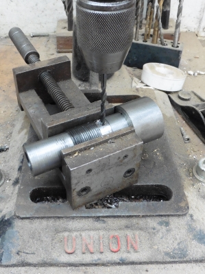
After that I could finish the threading. I made a much better job of it than the last one, took my time a bit more and didn't break the tool. Then came the moment of truth...it looked good, but would it fit the saddle? Indeed it did, and very smoothly too. I drilled a blind hole in the widest part so that I can get some purchase for tightening/loosening, it's got an allen key in it in the pic. Then with it screwed in fully, I punched the point where the oil hole needed to go:

And from there, to the drill:
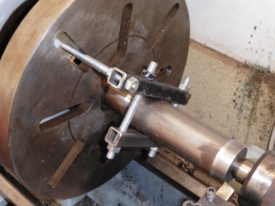
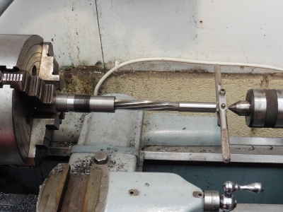
Now things were getting serious. Time to ream the bore out to its final size, 5/8". I'd not reamed anything before so wasn't sure how it'd go. I used the "floating reamer" method described in Sparey's "The Amateur's Lathe", which he considers gives the best results most of the time. Unlike the taper reamer used on the tailstock quill, this straight reamer is used under power. The lathe is put into slowest back gear, the reamer driven into the hole on the tailstock centre, and a tap wrench is used to hold the reamer steady. It should follow the hole in and not go off-centre.
Incidentally, my normal tap wrench was too small, so I rummaged in the bottom of my reserve toolbox and found this one - when I took it out I noticed it had my grandfather's name on it, (he was a toolmaker by trade). It must have sat in the bottom of various toolboxes for decades in dad's shed, before finally ending up in mine, and here it was, just when I needed it. A nice little connection with the past, cheers gramps.
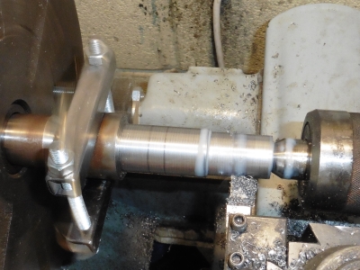
Anyway, I proceded gingerly, but it turned out to be very easy to feel what was going on, and how much to feed the tailstock in. I removed it regularly to prevent everything getting clogged, but it all went nicely. And left an amazing finish, so very smooth...and the fit was actually what I'd call "perfect". The bushing slides onto the shaft without any binding, spins freely, but has no perceptible play at all. Just spot on.
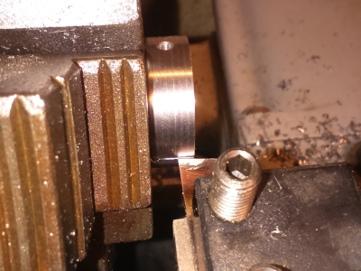
The final step was to tidy up the outside end of the bushing, and part it to length. To get the length the same as the original, I mounted the original bushing between centres, and brought up a parting tool level with the edge (below, left). Then replaced it with the new one, and parted off at that point (right):
In fact, I partially parted off to mark the point, then did the final shaping of the right hand end, before chopping it off for good.
And that was that. I'm really pleased with how it turned out, rather better than the compound bushing. All of the measurements are spot on, the thread came out perfectly, and the fit to the cross-slide screw shaft is orders of magnitude better than the old one.


So that, is very nearly that. The lathe is all back functional again, its new paint job covered in oil and chips. Just a couple of bits of final tarting up to do before I can call it finished...