Headstock Teardown
Geartrain
September 2014
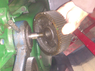
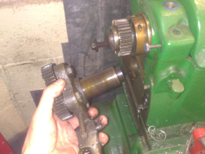
The first step of stripping the headstock is to remove the geartrain from the rear of the lathe. The large cast cover comes off with just three screws to reveal the gears.
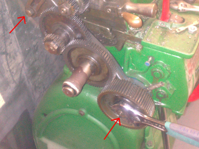
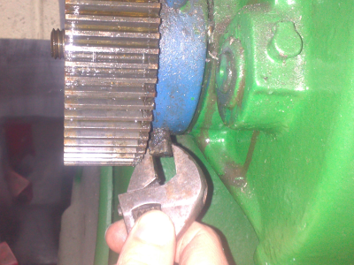
The lower three gears are all mounted on a pivoting frame. This is held on by a top pivot bolt and the bolt through the lower gear (below left, arrows). There's also a locking set screw hidden under the bottom of the frame which is easy to miss(below right)
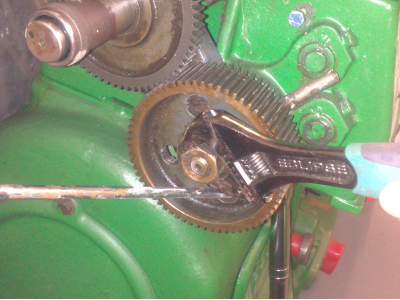
To remove the lower gear I used a screwdriver though one of the handy holes to lock it against the main body. Everything came unbolted fairly easily here. Then the gear just slipped off, it is keyed but obviously not a press fit.
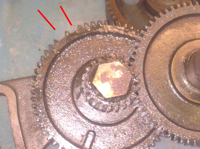
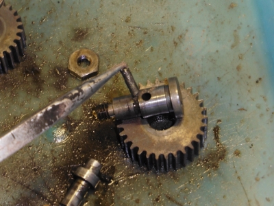
Then the frame comes off with the other two gears on it. The top one is held on with a nut & bolt through a bush, which came off easily enough. This is also the gear with two missing teeth (below right) - it'll need a repair or replacement, ideally:
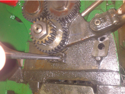
The other, central gear is the sliding one. The bolt for this is just wound into a threaded hole in the frame, with just two small holes in the end as the only means of purchase. I can't budge it, so I think I will simply clean it up in place as I'm likely to do more damage trying to get it off, I think.
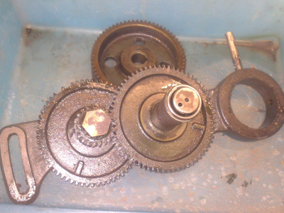
As I take these parts off, I'm giving them a clean in white spirit to get the gunge off, then storing in plastic boxes. I want to see what repairs or replacements I need to do before I move onto the next phase of paint stripping and cleaning properly.
Reverse Tumbler Assembly
Next is the reverse assembly. This is mounted above the gears just removed, and is actually only held on by two small screws and a small block:
The whole thing then slips out easily, just a slight encouragement with a screwdriver to get it going:
Apparently I failed to get many pictures of the next bit, so I'll have to make do with words. I should also say that here what's in the book started diverging with what I had in front of me - it looks like the book refers to a later model.
The reversing assembly has quite a few parts in it, I stripped it down completely apart from the large main gear which requires an arbour press to get it on and off; I could make something up with tube and a vice but again I think, on balance, I'm probably best leaving it. All of the bushings have been in very good condition so I doubt there's much to be gained by stripping it. The rest is easy enough; the two tumbler gears are bolted and bushed, and came off with just a small amount of persuasion. The reversing lever and latch is held together by a taper pin which punched out easily enough.
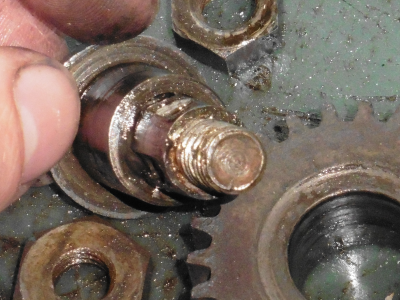
All in good condition apart from one, that is. The two tumbler gears looked to be mounted on near-identical bushings. The first has a hole in the front face which I've since found out is an oil hole; this leads to a drilled passage with a felt wick which lubricates the bushing:
The other one had no hole; as I cleaned it up it became clear that it's not a nicely-machined bushing at all, but a hideous bodge. Someone has graunched a roughly-made bit of bar into a top-hat bushing to make a replacement; it's pretty nasty stuff. The picture doesn't show how wonky and crappy the threading is on the end, either:
What a nice surprise. Still no biggy, that's something I can machine a replacement for pretty easily when it's all back together.
Backgear
Having removed the geartrain, the backgear can now be removed. As with most of the gears, they various parts are pressed onto a keyed shaft. This is held in place by a couple of square headed setscrews hidden under the backside of the supports; undo those, then the whole spindle is tapped out to the left using a drift. The backgear assembly with its two gears on then simply lifts out.
Not much to report there, it all looks in decent condition.
Spindle Removal
And then onto the big one, the spindle. I was interested to strip this down because of the use of both top oilers and side oilers, which didn't make a lot of sense.
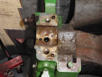
The bearings are removed by simply loosening the two bolts on each top cap, then lifting off. Actually they are a dowled fit so needed gently tapping with a soft hammer. I did the front first, then the rear. At this point I found that the rear cap bolts were rather loose, which didn't seem like a good thing and probably explains why there was so much play; tightening it up didn't reduce it much though, which suggested that it had been loose for a while and had hence worn as the spindle wandered around :(
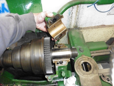
From my readings, it seems that Southbend made 3 different types of bearings; plain bronze "Box bearings", which are two part shells that are adjusted by having shims on the mating faces of the caps; removing shims reduces the clearance. The second type were also bronze, with a one-piece bearing that had a slot on the top, into which an expansion wedge fits. These are adjusted by winding the wedge up and down to open or close the bearing shell. Thirdly, there was a segmented cast iron bearing which used shims like the bronze box types.
So what I saw when I removed the bearing caps was that I have the bronze box types, which from other rebuilds I've seen, dates from the around 1940 or 1941 at the latest. However, there were no shims on the bearing caps. Condition of the top shells didn't look too bad, a small amount of polishing and a couple of scratches but nothing important:
 Left: Rear top bearing cap; Right: Front top bearing cap.
Both had holes and distribution groves for the top oilers, so that all made sense. With the caps off, the spindle simply lifts out - it is pretty heavy though so a bit of care is needed. Oddly I managed to avoid taking any pics of it; suffice to say the hard spindle journals seem to be in excellent condition. I measured both with a micrometer looking for any sign of ovality or taper and they're both dead straight and round, and the surfaces look brand new.
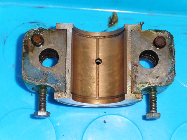
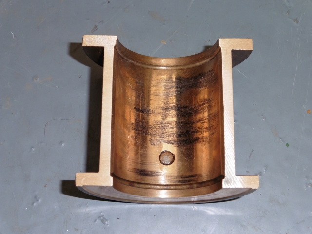
Moving on to the lower bearing caps, the first thing to notice was that they were in less good condition - as expected since the lower bearing takes most of the load. The front one is a bit more polished where there has been contact with the spindle, but otherwise fine and I've no concerns about it. The rear one had a large area of a burnt-on, varnish type deposit, and was looking a little gouged over the same area:
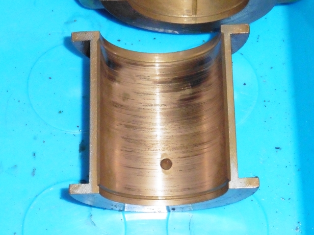 Left: Rear bottom bearing cap, with hard deposits; Right: Front bottom bearing cap - more polished than the top cap.
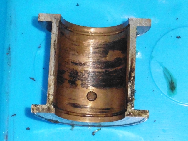
The rear one did look quite rough, so I gave it a bit of a clean and a polish to see how bad it really was. With most of the deposit gone I think it will actually be ok - although it is a bit rough in places, there are no sharp burrs so I think with a bit of elbow grease it will be fine.
I was still a bit concerned about the massive clearance on the rear bearing however. The lack of shims leaves me to think that at some point maybe someone took the caps off, lost/threw away the shims, then slapped it back together without them. Thus running the bearings too tight, which is why the rear one in particular has worn oversize. Or maybe they just forgot to oil it. Anyway, I wanted to get some idea of whether it could be brought into spec, or if I'd need to source a new set.
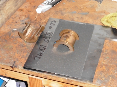
After checking with a post on the Southbend section of the Practical Machinist forum, I decided to sand down the mating faces of the bearing shells, to allow them to sit closer together and remove the clearance.
A surprisingly short spell with some 240 grit on a flat plate, checking often, seemed to do the trick. I've pretty much just taken the machining marks off of the mating surfaces; and although I've not measured the clearance, when reassembled there is now no noticable play using the broom handle, and it all spins freely. This is good enough to convince me that I can get it to spec using this method, with a bit of shimming if needs be, when I rebuild it. So I'll not worry about trying to find new bearings.
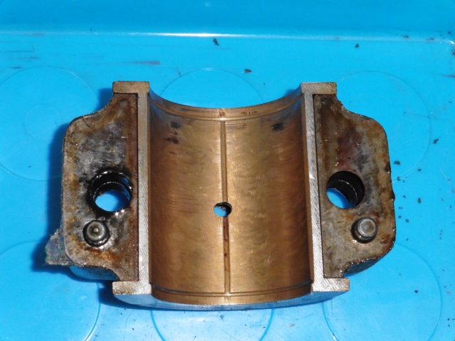
The bottom shells have a hole in with a setscrew for location into the casting, but no other holes, just the oil distribution groves. This did surprise me, as I'd expected to see wicks in the lower part. On side-oiler machines, these wicks go into a sump under each bearing shell which is fed by the oil cups. Despite having the oil cups and the sumps in the castings, mine does not use them. Ironic since I've been religously keeping the cups topped up for the last 5 years! Fortunately I've been oiling from the top as well, just to be sure.
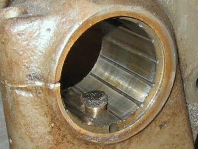 Left - my bearing casing. The big hole in the middle would normally have a spring-loaded wick in, for a side-oiler machine. Right - picture of a wick in a different machine - note also that this one has the segmented cast iron bearing. Image taken from this Practical Machinist thread
So that's a bit odd. I've got a side-oiler headstock with older, top oiler bearings and bearing caps. Was this a transitional machine during the period when they changed over? Or is it a Franken-lathe, built from, or repaired with, odd parts which didn't match? Don't suppose I'll ever know, but I guess what I will do is plug the side oiler holes and get some shiny new top oilers (the ones I have are old and leak).
Spindle Disassembly
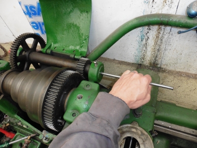
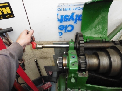
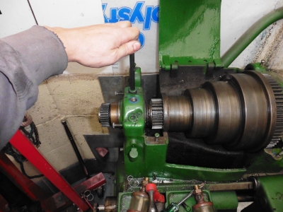
The final part here is to remove the various gears and pullies from the spindle shaft. Probably not stricly necessary, but I wanted to check that the shaft under the cone pulley was ok (as the pulley runs on this shaft when using the backgear).
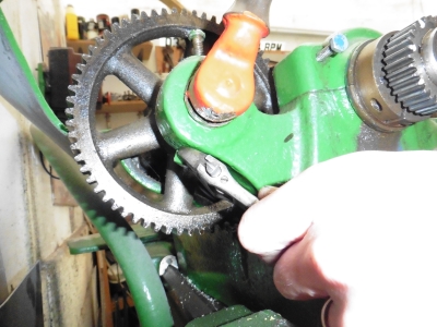
Not much to report on this except that I needed to buy a puller to get the gear off the end, and had to make a small insert out of 4mm bar to bridge the gap in the spindle; other than that it all just pulled off easily. The shaft is fine under the cone pulley so no worries there. I didn't bother removing the bullgear as it requires a press, and there's no reason to take it off. I did dismantle the movable pin mechanism which locks it to clean and inspect.
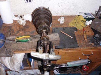
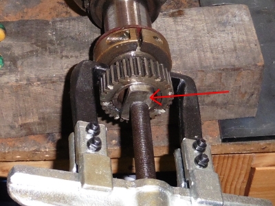 Removing the spindle gear with a puller. Right - insert made to give the puller something to push against.
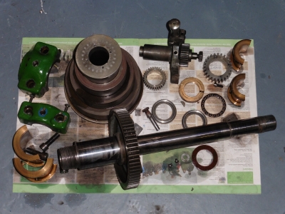
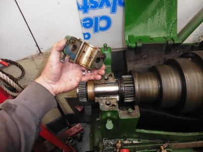
So I was finally left with a box of (fairly) clean parts waiting for the next stage: